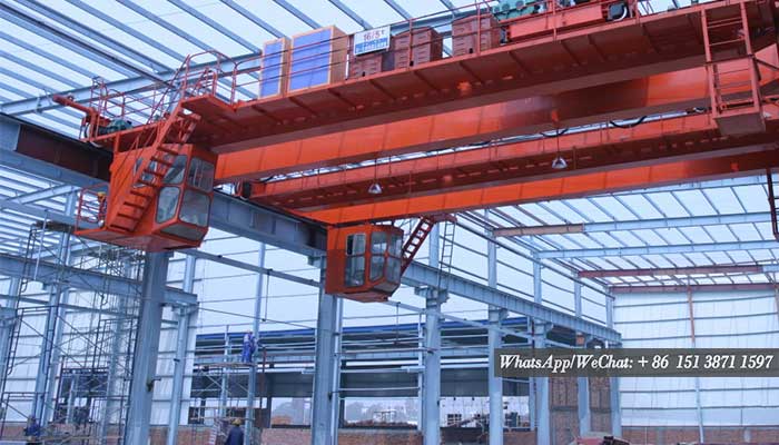
Overhead Crane Column Design, Tailored Ovehead Crane Columns for You
Crane-columns are unique in that they must withstand significant dynamic forces created by the crane's movement, as opposed to more conventional columns. These loads include the crane-mass gantry's as well as its maximum load bearing capability; also, the impact of the load during lifting must be considered in.
The longitudinal movement of the crane along its rail and the impact forces generated at the 'stop' are included in the lateral forces. These stopping forces are typically calculated at full speed, implying that they will be significant. There will be sideways lateral forces in addition to the longitudinal forces.

Column structures for overhead cranes - Custom crane designs available.
The carriage's travel across the crane-gantry generates these forces, which will also include some sort of'stop'. As a result of these lateral loads, it is common practice to tie the top-flange of the crane-gantry girder to the building-column using some type of 'Tie-Back' or 'Surge-Girder.' As a result, the crane gantry girder and the building design are inextricably linked.
To make matters even more complicated, due to the open nature of such structures, there are no intermediate floors to tie the columns together, reducing the effective-span, necessitating the design of the structure as a 'Portal-Structure,' with the roof-truss or portal rafter serving as the effective tie.
A traditional Portal-Frame structure is typically used for Light-Duty cranes (less than 10 T capacity), where the crane beam or girder is supported by a cantilevered 'Corbel' which may be welded or fastened to the inside face of the column. A 'Twin-Column' configuration is commonly used for heavy-duty cranes, in which the crane-girder is supported from the cap of a supporting 'Crane-Column,' while the outer 'Building-Column' provides lateral rigidity.
Portal Frame Columns
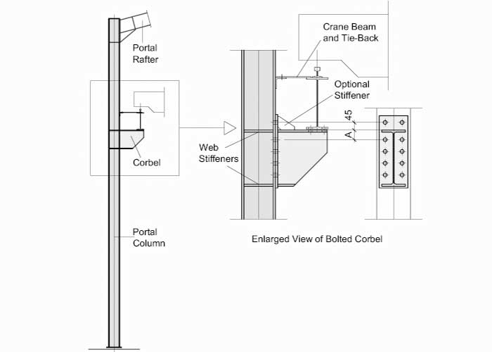
For light-duty applications, traditional portal frames are frequently used (less than 10 T. capacity). The corbel is essentially a cantilevered bracket that can be welded or attached to the column flange. The crane-beam is seated onto the top of the bracket at a sufficient distance from the column to allow the crane-gantry to pass through.As shown in the diagram, the eccentricity of the load causes significant moment reactions at the joint, which must be accommodated by the column flange. As a result, it's common practice to incorporate stiffeners into the column adjacent to the top and bottom flanges of the bracket to resist tension (top) and compression (bottom) forces, while the joint between the bracket and the column.
The corbel is normally made from a standard hot-rolled -I- section, but it can also be made from plate in some cases.
To prevent top-flange distortion, the crane-top-flange beam's is normally secured against the column by Tie-Back beams.
Stepped Portal Column
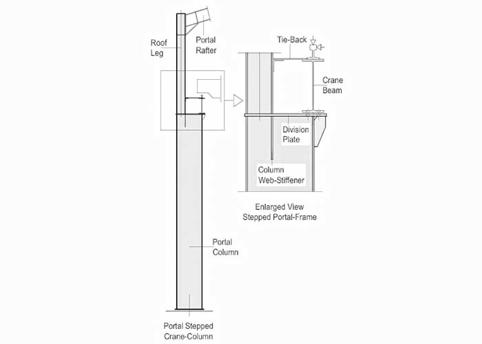
The 'Stepped Portal-Column,' which is capable of substantially larger weights and broader spans, is the second choice for Portal-Frames. The needed clearance between the crane-gantry and the roof-leg determines the geometry between the broader bottom part and the roof-leg. The lower section's cap is formed by welding the roof-leg to the division-plate, which must be faced for bearing. A web stiffener is welded to the lower section's web near to the roof-flange. leg's If the designer wants this stiffener to be continuous, a slot may need to be carved into the web and welded all the way around after installation.
The crane-web beam's should be directly above the inner flange of the column. The division-plate will need to be enlarged to accommodate the crane-bottom beam's flange, and slotted holes will be needed for lateral adjustment.
The stepped column is a very effective support mechanism that may be used for cranes up to 50 tons. However, it can be quite expensive, especially if the bottom (wider) section is to be manufactured.
Under the category "Tie-backs," a detailed examination of tie-backs is conducted. Girders for cranes
Twin Columns
For heavy-duty applications, twin column layouts are often arranged in one of three ways.
Twin-Leg columns are typically shop-fabricated and erected as a unit; they can be bolted or welded, but welding is the most frequent method. The transportation restrictions limit their height.
In each scenario, adequate room must be provided for the crane and carriage to pass laterally and longitudinally along the length of the building, complete with the lifting mechanism.
A plate or Latticed Surge-Girder must be used to confine the Crane-Girder against the column or roof-leg.
The horizontal center-distance between the columns should be somewhere between the column-height (measured to the top of the crane-girder) divided by 7 as a general rule of thumb (or multiplied by 0.15)
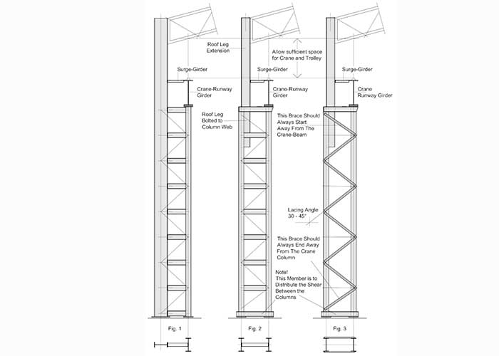
Figure 1 shows a simple twin-leg crane-column with a continuous outer column that extends to support the roof truss or rafter. At their center-line, the columns are battened together, occasionally with additional bracing. This structure is similar to a more traditional stepped column and can be seen on cranes up to 50 tons in capacity. With this structure, there is sometimes a height restriction, with the overall height normally being limited to roughly 15 m.
Figures 2 and 3 show typical layouts for heavy-duty cranes with capacities greater than 50 tons. They can be latticed (as shown in Fig 2) or laced (as shown in Fig 3). Lacing is optional on the battened columns.
The flanges of the columns are placed longitudinally along the building, with the inside column supporting the crane-girder and the outer column providing lateral constraint to the entire structure. To support the roof truss or rafter, the roof-leg, which is fastened to the inside web of the outer column, is extended.
The angle of bracing for Laced-Columns should be between 30 and 45 degrees, which will be decided by the configuration of the bracing components as oriented according to the image (above). If the column flanges are small, it may be necessary to offset the common work-points, which will result in some eccentricity; nevertheless, this is rarely an issue; if in question, consult the competent engineer.
A horizontal tie should be added at the base of the columns to distribute horizontal shear across the columns; typically, this would be in the form of channels welded above the base-plates.
The Crane-Girder should be secured to the roof's leg.


