Crane Rail Types, Crane Rail Dimensions & Crane Rail Installation
Overhead crane rail and gantry crane rail crane services from crane rail design to crane rail installation. Various crane rail types, rail dimensions and crane rail specifications to meet all type of cranes and all your need.
Crane-Rails
Standard flat-bottom rails are typically utilized for low to medium-duty applications, but when subjected to severe lateral loads, their height-to-width ratio may cause them to overturn. Their narrow webs are also subjected to a combination of high vertical tension and bending stress from lateral loads, potentially resulting in web failure.
Special heavy-duty crane rails should be utilized for heavy and extra-heavy-duty applications.

Crane rails are available in two types: fixed and floating.
Fixed Rails
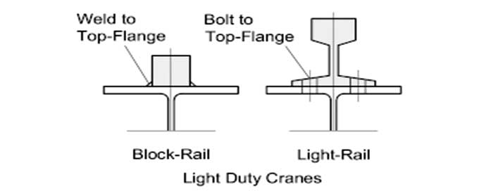
The term "fixed rail" refers to a rail that is welded or bolted directly to the crane girder's top flange. A simple square bar welded to the girder flange can be utilized for very light-duty, short-span applications, but this leaves no room for adjustment or alignment and necessitates a high level of accuracy during fabrication. The beam section may buckle under heat if proper welding methods are not followed, which will be exceedingly difficult to fix.
The second fixed rail option is to bolt the rail through its base to the top flange of the supporting girder; however, there is no space for alignment or lateral movement, as there is with the previous option.
Apart from preventing lateral adjustment, such bolts prevent the rail from 'floating' longitudinally, which is desired in medium to heavy-duty applications.
Floating Rails
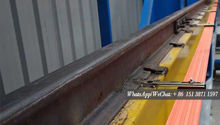
A floating crane-rail is created by attaching the rail to the supporting girder with unique rail-clips, which keep the rail in place and prevent the formation of a "bow wave" ahead of the moving wheels.
The top flange shortens under compressive stress as the crane-girder deflects under vertical pressure, causing relative movement between the top flange and the rail. The clips can loosen after numerous cycles, and the flange under the rail can wear out owing to the 'fretting' motion. To ease this, steel wearing-plates can be installed under the rail, or patented resilient mountings can be used, which have the added benefit of spreading the concentrated wheel-load as well as minimizing impact, vibration, and noise, as well as allowing the crane to travel more smoothly.
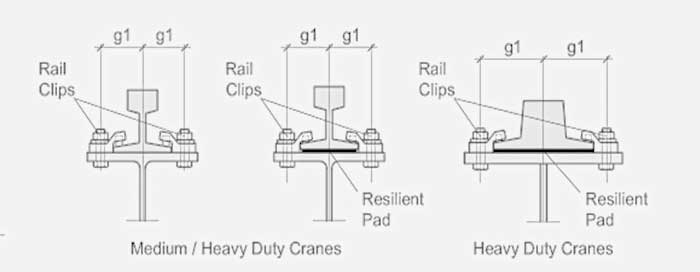
There are several varieties of patented rail-clips that fall into the 'floating-rail' category, and they are occasionally combined with resilient rail-pads to break the metal-to-metal contact between the rail and the girder flange, allowing the crane to go more smoothly. The possibility for lateral adjustment of the rail on the girder, which simplifies alignment, is a unique feature.
Rail junctions should be aligned with girder ends where rails are not continuous. To 'smooth-out' the girder's discontinuity, it is sometimes practiced to extend the end of one rail some distance beyond the girder. The benefits, however, are questionable because the rail now tends to bind the top flanges of abutting girders together, when they should be free to move under end-rotation produced by vertical loading. As a result, the holding-down clips at the ends are prone to becoming free.
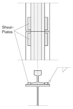
Rail alignment in the horizontal plane would be helped by shear plates welded to the top flange at the girder ends.
The welded option, as employed in a continuous 'floating-rail,' is the best type of rail joint. This layout, when combined with continuous gantry girders, resilient rail-pads, and sturdy columns, offers the best combination of gantry design attributes.
Rail Splices
End-bolting or welding can be used to make big heavy-duty crane rails totally continuous, and then the rails can be permitted to float longitudinally in reference to the girder. The rail is attached to the girder by clips that hold it in place laterally and prevent it from lifting, but they do not 'clamp' it to the girder. The rail must be site-bolted or welded into a continuous length from end to end because it is free to move longitudinally. The rail finishes by abutting against the rail-stop.
Although the welding technique for heavy-duty crane rails is unique and requires talent, the considerable additional cost is offset by lower maintenance and rail replacement costs. The rails joints on flat-bottom rails are close-butted and joined with bolted Fish-Plates (without slotted holes). The fundamental benefit of 'floating' rail connections is that they eliminate girder joint discontinuities, which always cause wear on wheel flanges and rail ends as well as loosening of fasteners.

Crane Rail Stops
The crane-stop, which must absorb the crane's impact, bears the most severe longitudinal load. Not only must the stops be designed correctly, but the force must also be transmitted back along the girders to the vertical column bracing. The typical day-to-day loading will be rare, but the impact load of a full-speed stop will be severe, so they must be designed for the worst-case scenario. Fatigue should not be a concern because the load is only applied in one direction and is not reversible, and high-strength bearing bolts should be used to prevent shear pressures.
The following are two examples of end-stops: The first is bolted to the girder's top flange; a sufficient number of bolts must be used to resist shear, and the forward bolts must resist strain caused by the stop's overturning moment.
The second is bolted to the girder's end through an end-plate that is welded to the girder's end. The stop is typically made out of a standard -H- section that is fastened to the end-plate. On the stop, a shear-bracket is welded forward, which is then fastened to the girder's flange.
Energy-absorbing buffers should be installed in both of these alternatives.

Crane Rails Installation
Crane Rails Installation
The crane track is fastened in the main beam in the following ways:
- For the work level M5 following the automobile track, utilizing continuous welding and a non-removable construction, the track section force can be included in the overall force of the main beam, increasing the main beam's bearing strength.
- b diagram is the most widely used fixed approach, which is simple to assemble but more difficult to demolish.
- Working levels M6, M7, and M8 are covered by 3 c and d.
- On the exceptional conditions, using a screw connection for the bottom of the bolt in 4, e and f figure is not easy.
- The impact can be reduced by adding 5 g to the bottom of the track pad, which has a thickness of 3-6mm rubber.
- The ring track fixing method is 6, h.
- On the route, I am fixed on the crane rail carriage rail beam.
Crane Rail Safety and Adjustment
Crane rail and crane track safety inspections: inspect the track, bolts, and splints for cracks, looseness, and corrosion. Found cracks should be replaced as soon as possible, and any other problems should be corrected as soon as possible. The main inspection tool with a flaw detector on a line track.
Measurement and adjustment:
To check the track's linearity, the method can be used to pull up a 0.5mm wire from both ends of the rail car, and then use the hanging line hammer method to measure point intervals of around 2m.
- The level can be measured based on the track's elevation.
- Track span, which can be used to evaluate a tape or an infrared measuring equipment Permitted deviation of the bridge crane gauge is 5mm; track longitudinal gradient is 1/1500; and two orbit relative elevation allowable deviation is 10mm.
- Rrack joints, which can be produced with a direct head or a 45-degree angle of the joint. Miter joints enable for a smooth wheel changeover at the joint. In general, the space between joints is 1 2mm; however, in cold places, the impact of temperature on the gap should be considered, and the distance should be 4 6mm. At the joint, the height difference between the two tracks must not exceed 1 mm.
