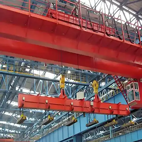
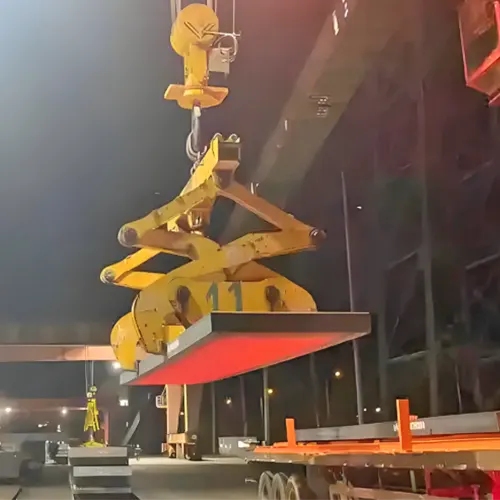
5 Ton -74 Ton Overhead Crane & Bridge Crane for Casting Ladle
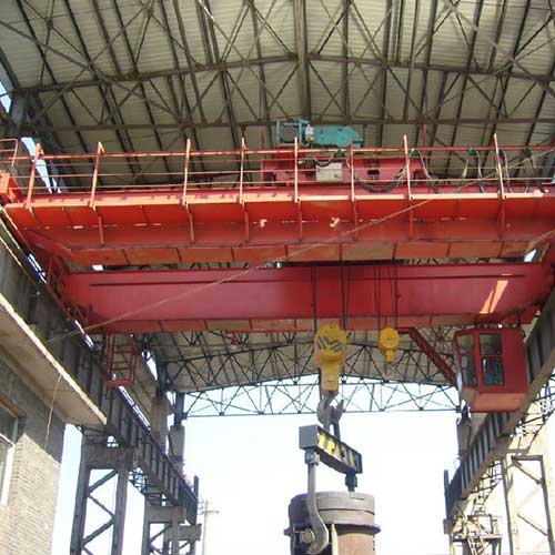
Casting ladle crane for steel mill plant. Double girder overhead crane & bridge crane with 4 brakes for casting ladle 10 ton, 20 ton, 30 ton to 74 ton.
| Casting crane | QDY double girder overhead crane |
| Capacity of crane | 5 ton - 74 ton |
| Lifting Height | ≥5m |
| Crane Span | ≥10m |
| Protection grade | IP54-IP65 |
| Note | Customized crane design is available. |
Category: Casting Crane
Your Trusted Overhead Crane Manufacturer & Supplier
5 Ton -74 Ton Overhead Crane & Bridge Crane for Casting Ladle
4 Brakes Double Girder Design Safe Casting Ladle Crane
Casting ladle crane for steel mill plant. Double girder overhead crane & bridge crane with 4 brakes for casting ladle 10 ton, 20 ton, 30 ton to 74 ton.
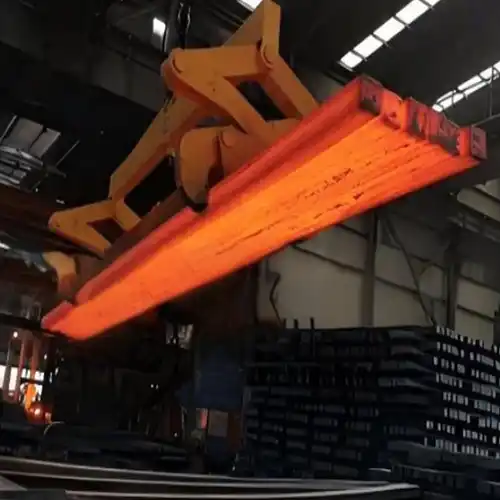
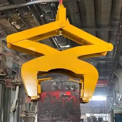
Double girder overhead crane for casting ladle with capacity of 5 ton to 74 ton. The QDY series double girder bridge cranes for ladle casting are one of the main equipment in the steelmaking and continuous casting process. The casting crane is mainly used to pour molten iron to the converter in the converter feeding bay, hoist the molten steel to the refining furnace on the refining bay or lift the molten steel to the continuous casting rotary ladle table on the molten steel bay,etc.

Double girder overhead crane for ladle casting - Ladle casting crane

Ladle casting crane drawing
Technical Data of double girder overhead crane for ladle casting
The QDY ladle casting overhead crane is a type of special industrial overhead crane crane for metallurgy that is primarily used to lift molten metal (or metalloid material) with the rated lifting capacity of no more than 75 ton.
Ladle Crane | |||
Working Class | A7,A8 | ||
Capacity | t | 5~75 ton | |
Span | m | 5~60 | |
Lifting Height | m | 12~50 | |
Main Lifting Speed | m/min | 6~15.5,Single Speed or VFD | |
Aux Lifting Speed | m/min | 9.5~15.5,Single Speed or VFD | |
Main Trolley Travelling Speed | m/min | 29~43.5,Single Speed or VFD | |
Aux Trolley Travelling Speed | m/min | 29~43.5,Single Speed or VFD | |
Crane Travelling Speed | m/min | 58~105,Single Speed or VFD | |
Control Method | Cab Control | ||
Power Supply | 380V 50HZ 3PHASE or Customized | ||
Temperature | ℃ | -20~60 | |
Protection Grade | IP54~65 | ||
The above are standard parameters, and customized solutions and designs are provided according to your actual needs. | 5 | ||
Applications of double girder bridge crane for ladle casting
QDY series overhead bridge cranes are one of the specialized industrial overhead crane equipment for the steelmaking and continuous casting process. Usually, the Industrial bridge crane designed with ladle hook is mainly used at the place where the molten metal is lifted at the hot rolling mill with capacity from 5 ton to 74 ton, and the working class of the complete overhead crane system is A7 . To protect the main girder, the thermal-protective coating and substances is added to the bottom of the main bridge girder. And the application environment conditions are as following;
Environmental conditions:
- The power of casting bridge crane is three-phase AC; rated frequency is 50HZ; rated voltage is 380V;
- The temperature of working environment is -10℃-+60℃;
- The relative humidity is no more than 50% when the temperature is +40℃;
- If the requirements are more than above-mentioned, special designed and additional featrues should be added to meet your particular applications and lifting requirements.
To get your customized overhead crane for ladle casting in rolling mill, the following information are required: The basic parameters (rated lifting weight, lifting height and span, etc.) of the bridge crane shall be described clearly to our sales. If the mentioned specifications are not sure , please feel free to contact our sales and engineer who will help you to confirm what exactly you need.

Double brakes on crane trolley main hook & auxiliary hook lifting systems

Double beam box girders for casting bridge crane
Features of double girder bridge crane for ladle casting
The QDY ladle casting crane's structural design uses a double girder, double rail, and an open winch trolley with main lifting mechanism and auxiliary mechanism, and are equipped with a main lifting hook and an auxiliary hook. Each hook and lifting mechanism has an independent transmission system, which not only enable them to carry out the material handling independently, and also make them able to handle the same load together cooperatively.
Crane bridge of casting cranes
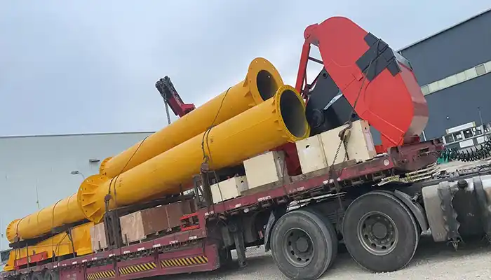
The crane span structure or crane bridge is the crane's main body and the main stress structure. The type of span structure is a double-girder, double-rail construction, which is primarily composed of a main girder, an end girder, a walking flatform, a handrail, a ladder, and other metal structures that are attached.
The structure of main girder is steel plate constructed box shaped girder. It has a thermal insulation device installed on the bottom of the main girder. The main girder cross section is analyzed and calculated systematically using the finite element calculation method, which ensures the cross section has sufficient strength, rigidity, and stability of the complete overhead crane. What's more, the overhead crane traveling mechanism and electronic equipment are set up reasonably on the walking board to ensure the operator's convenience.
The crane's upward deflection is (0.91.4)S/1000. And the position of the maximum deflection of is controlled in the 1/10S range.
The box structure design is also used for the end carriages. The connection between the main and end carriages is rigidly coupled and also by high strength bolts.
Lifting structure of ladle casting cranes
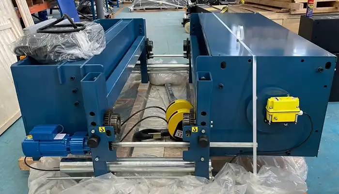
The main lifting mechanism and auxiliary are set on the same trolley frame and bracket, which is set with separately driving device. The allocation of the driving system of the main lifting mechanism and the auxiliary lifting mechanism has the following characteristics: compact structure, easy maintenance, safety and reliability.
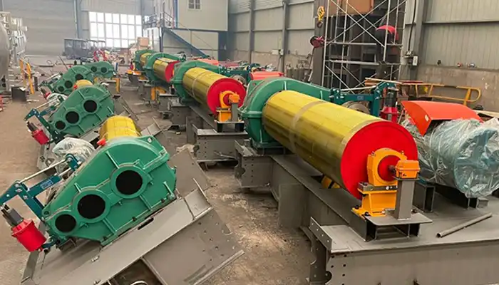
The lifting mechanism of the double girder overhead crane consists of an electric motor, a brake, a reducer, a drum, a pulley block, a hook group, steel wire rope, and other components. Driving by single electric motor and lowering the speed by reducer, then it drives the duplex drum. The materials are elevated using a steel wire rope coiling system composed of a fixed pulley and a movable block.
Trolley traveling mechanism of open winch bridge crane for ladle casting
The trolley traveling mechanism of casting bridge crane adopts centralized driving two wheels plan. It is powered by an electric motor. The power is then transferred to the reducer via the gear coupling and driving shaft. The machine will then be dragged to complete the longitudinal motion. It is equipped with a rail cleaner on the front end of the wheel, which aims to automatically clean the stumbling block on the surface of the rail in a convenient manner. It can ensure the crane's safety while traveling.
Long travelling of ladle casting bridge crane
The travelling system of the casting crane is driven by two electric motors of the driving wheels. And then, the gear coupling and driving shaft then transfer the power to the reducer. Once the reducer has slowed it down, the driving wheel will be propelled by the driving shaft and gear coupling. The longitudinal motion will then be completed by dragging the entire double girder bridge crane . On the front end of the wheel, a rail cleaner is installed with the purpose of automatically and conveniently clearing the obstruction from the rail's surface. It can ensure the safety of the bridge crane's movement.
Protection and safety devices for casting crane in rolling mill
- Emergency stop : The casting crane is equipped with an emergency power off switch. In an emergency, it will turn off the entire power supply.
- Motor full function protection device: The electric motor is outfitted with a full-function protective device that effectively protects against overcurrent and short circuit. All of the handrail doors have electronic interlocks.
- Overload limiter: The QDY ladle casting crane has an overload limiter installed. When it reaches 90% of its rated load, the display will automatically send an alarm. When it reaches 110% of its rated load, the QDY ladle casting crane will cut off the lifting mechanism's power source.
- The lifting limit position: the lifting mechanism of the hook is set with a limit device. When it is lifted to the limit position, the power source is automatically cut off.
- Stroke limiter: Stroke limiters are installed on both sides of the overhead crane and trolley traveling mechanisms. When the casting crane and trolley reach the limit position, it can automatically cut off the power source and reverse direction.
- Overload protection: If the material exceeds the rated capacity, the bridge crane will sound an audible warning to protect itself.
- Safe crane control : To avoid any injuries to the operation staff, use room control or remote control.
- Hooks with safety latches: to prevent goods from falling down.
- Main lifting motor : The main lifting motor has thermal and currency protection.
- Other safety features. All of the crane safety devices and features can be added to custom the casting overhead crane to meet your lifting requirements and application conditions. All of the above information is presented for your reference. For more information, please consult a specialized crane engineer by leaving a message below.

- The open winch trolley is designed with a main lifting mechanism, an auxiliary mechanism,
- An independent transmission system is designed for each lifting mechanism.
- Independent and cooperative operation of the two hooks all are possible.

- Over Speed Sensor
- Detect the speed of the motor's rotation; if it exceeds that rated speed, the sensor will promptly signal the electric system.
- The double EHT brakes will then hold the brake drums in place and stop the ladle from falling.

Electric Dis. Brake
- When the motor shaft breaks and the EHT brakes can't function properly, or whenever the sensor notices that the drums are running too fast. It will send a timely signal to the brake.
The drum flange will then be held in place by the magnetic disc brake to stop the ladle from falling and prevent accidents.

Balanced Arm
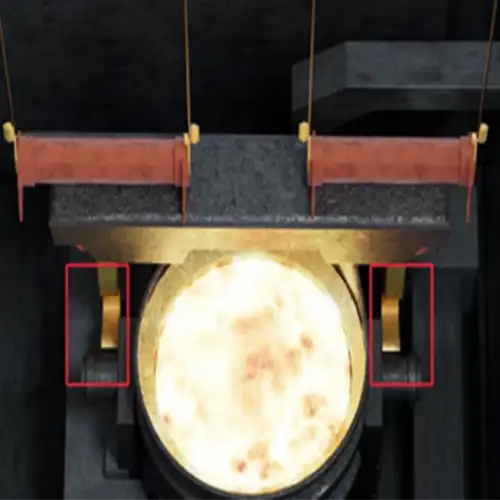
- It can hold the ladle even if one piece of the wire rope breaks by adjusting the length of the wire rope and balancing the weight of the load.
- To prevent accidents, make sure the ladle can be set down safely on the ground.
Design of the upper pulley set
- Determine the speed of the motor rotation; if it exceeds the limit, the sensor will promptly alert the electric system.
- The double EHT brakes then hold the brake drums to stop the ladle from falling.

Safety Monitor Unit
The screen will show crane working status:
- Loading data
- Lifting height
- Traveling limit switch status
- lnter-lock
- Anti-collision limit switch status

Insulation Protection layer
- Add a layer of rock wool insulation at the bottom of the casting ladle cranes to keep the steel structure from overheating.
- minimizing the effects of thermal radiation on the mechanical characteristics of steel plate.
- Protect the steel structure's tensile strength and fatigue grade yield limits.
- Extending the lifespan of all the cables and electrical components.
Main parameters of 10 ton double girder bridge crane
In the following, the main parameters of the 10 ton overhead bridge crane for ladle casting are presented for your reference. Customized casting crane with double girder designs can be used to handling loads with capacity from 5 ton, 10 ton, 20 ton, 30 ton, 40 ton, 50 ton up to 74 ton.
QDY Double Girder Casting Overhead Crane with Hook 10t | ||||||||||
Span | S(m) | 10.5 | 13.5 | 16.5 | 19.5 | 22.5 | 25.5 | 28.5 | 31.5 | |
Lifting height | m | 20 | 20 | 20 | 20 | 20 | 20 | 20 | 20 | |
Lifting speed | m/min | 13 | 13 | 13 | 13 | 13 | 13 | 13 | 13 | |
Trolley speed | m/min | 44.9 | 44.9 | 44.9 | 44.9 | 44.9 | 44.9 | 44.9 | 44.9 | |
Crane speed | m/min | 118.6 | 118.6 | 118.6 | 119.3 | 119.3 | 114.9 | 114.9 | 114.9 | |
Lifting motor | kw | 26 | 26 | 26 | 26 | 26 | 26 | 26 | 26 | |
Trolley motor | kw | 2.2 | 2.2 | 2.2 | 2.2 | 2.2 | 2.2 | 2.2 | 2.2 | |
Total weight | kg | 17480 | 19680 | 22200 | 25800 | 28570 | 33750 | 37910 | 41780 | |
Max Wheel Load | KN | 112 | 120 | 130 | 138 | 145 | 160 | 171 | 180 | |
Track | P43 | P43 | P43 | P43 | P43 | P43 | P43 | P43 | ||
Main dimension | mm | 10.5 | 13.5 | 16.5 | 19.5 | 22.5 | 25.5 | 28.5 | 31.5 | |
Rail top to main top | H1 | 1876 | 1876 | 1876 | 1876 | 1876 | 1926 | 1926 | 1926 | |
Rail top to hook centre | H2 | 602 | 602 | 602 | 602 | 602 | 552 | 552 | 552 | |
Wheel base | W | 4050 | 4050 | 4050 | 4050 | 4050 | 5000 | 5000 | 5000 | |
Crane width | B | 5800 | 5800 | 5800 | 5940 | 5940 | 6380 | 6380 | 6380 | |
Hook left limitation | S1 | 1600 | 1600 | 1600 | 1600 | 1600 | 1600 | 1600 | 1600 | |
Hook right limitation | S2 | 1300 | 1300 | 1300 | 1300 | 1300 | 1300 | 1300 | 1300 | |
Trolley gauge | K | 2000 | 2000 | 2000 | 2000 | 2000 | 2000 | 2000 | 2000 | 5 |
Main Projects
Related Products
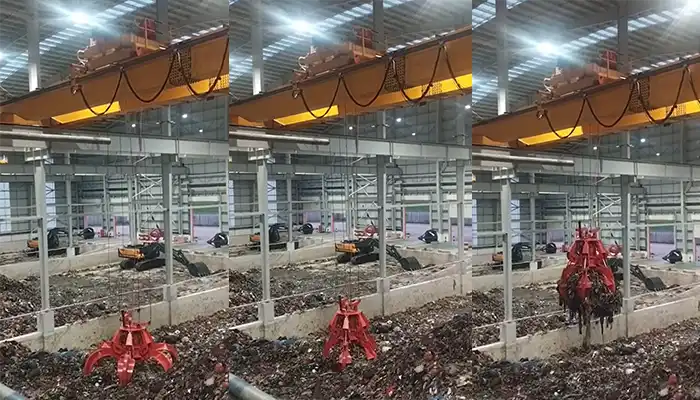
Supplied three grab bucket crane kits to Indonesia, enhancing garbage handling efficiency with high load capacity and reliable performance.
Free consultation to Confirm Parameters & Specifications and Get
Latest Crane Price & Crane Rate.
- Types of overhead cranes : _______?
- Optional: Overhead travelling crane, goliath gantry crane,Slewing jib crane, Single girder or double girder crane,small portable crane or kbk crane, etc.
- Capacity of overhead crane: _______?
- Optional: 0.25ton, 0.5 ton, 1 ton, 2 ton, 3ton, 5 ton, 10 ton,15ton, 20ton, 25 ton, 30ton,35ton, up to 550ton, etc.
- Crane span & lifting height : _______?
- Crane travelling length : _____?
- Control of overhead crane:_______?
- Optional: pendant/ remote/cabin control
- Voltage supply of overhead crane:_____?
- Eg,: 380V50/60HZ,3Phase or others,etc.
- Application/usage of crane:_______?
- Eg,: Steel mill, ,injection mold, cement,stone, concrete,granite, general manufacturing, etc.
Just leave a message via the contact form and our hoist and crane engineer will contact you with in 24working hours.
Get In Touch
