Crane Basic - Main Structures, Parts and Components & Crane Kits
Overhead crane main structures & main parts and components for you to know better about bridge cranes. Get your overhead crane design & custom crane kit.
Category: Crane Basics
Your Trusted Overhead Crane Manufacturer & Supplier
Main Parts and Components of Overhead Cranes
Basic Bridge Crane Structures and Components
Basics of overhead crane specifications, definitions & terms for reference to get custom overhead crane, gantry crane, jib crane & other hoists and cranes.
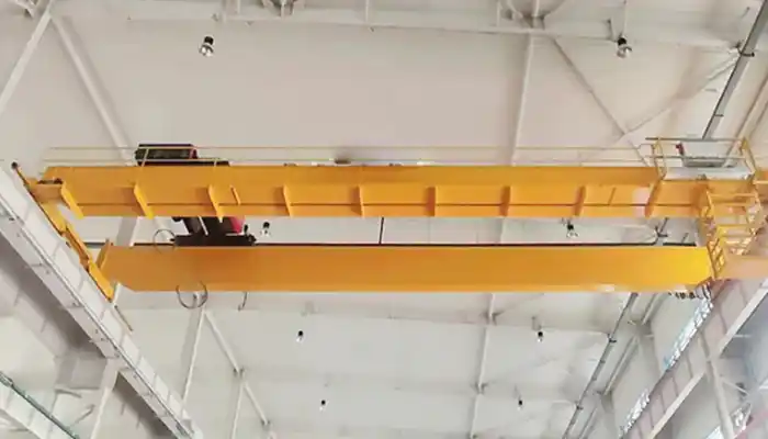
A crane's function is to move the lifted weight horizontally and longitudinally across the building. Typically, the hoisted load is supported by a hook that is cabled to a hoist. A trolley that swings horizontally along the crane bridge supports the hoist. Depending on the capacity and span, the crane bridge is connected to a number of crane trucks at each end. Crane trucks might have two, four, or eight wheels depending on the crane's capability. The wheels are supported by runway beams and go along a crane rail. The diagram below depicts the fundamental crane components.

- Bridge - An overhead crane's main structural component is the bridge. It spans the width of the structure and is made up of one or more load-bearing beams or girders. These could be steel box girders or rolled steel joists. During operation, the hoist trolley runs along the length of the girders on the bridge.
- Runway - The track and support system used by the crane. The runway girders are typically designed as an integral element of the building construction.
- Runway Rail - The rail that the crane runs on and is supported by the runway beams.
- End trucks - The end trucks, which are located on either side of the bridge, house the wheels on which the entire crane travels. It is a structure made up of structural parts, wheels, bearings, axles, and other components that supports the bridge girder(s) or trolley cross member(s). Electric drive motors, which are normally two-speed or variable-speed units, power the wheels and bring the crane into place. Brakes, which are generally electrically actuated, are positioned on the drive motors and are crucial for preventing uncontrolled loads from becoming unsafe. At the end of the travel range, electrical limit switches stop power to the drive motors, preventing the crane from colliding with the building structure.
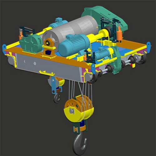
- Hoist - A hoist mechanism is a unit that includes a motor drive, connection, brakes, gearing, drum, ropes, and a load block that is designed to raise, hold, and lower the maximum rated load. The trolley is equipped with a hoist mechanism.
- Trolley or Crab - The 'crab' is the 'cross travel unit' that lowers and raises the hook. A top-running trolley on a double-girder crane runs on rails attached to the crane bridge's top. A single-girder crane's underhung trolley runs on the bottom flange of the crane beam, with drive units directly linked to the trolley. The trolley transports the electric wire rope hoist, which supports the load block and hook via a pulley system. The load is moved up and down by a variable-speed AC motor on the hoist. Limit switches keep the load block and trolley from colliding.
- Bumper (Buffer) - An energy-absorbing device designed to reduce impact when a moving crane or trolley reaches the limit of its allowed travel or when two moving cranes or trolleys collide. This device can be mounted on a bridge, trolley, or runway stop.
- Controls - EOT crane controls are often housed in an operator pendant or remote console and consist of numerous push buttons and switches that operate relays and contactors located on the crane. Drive motors and hoist motors draw significant currents when in operation and require adequately rated contactors to turn them on and off. Variable frequency inverters manage the speed of motors that require precise placement. If a dangerous scenario occurs, a master contactor is triggered by a main switch and cuts off all power to the crane.
Other features of specialty cranes may include: end stops, a full length platform on both girders, under bridge illumination, a closed, glazed, or air conditioned cabin, specialist controls, and so on.
Crane bridge / Main girder
The bridge frame includes main girders, end girders, trolley running tracks, railings, walking platforms, driver's cabs, etc.
The bridge frame is the basic component of the whole crane, which bears various loads and should have sufficient rigidity and strength. Strength is the ability to resist fracture, and stiffness is the ability to resist deformation.

Main parts and component of main girder of top running double girder overhead crane

End carriages of double girder overhead bridge cranes
Main beam structure:
- Material: Q235B or Q345B , Structural form: box type
- Because the main girder of the box structure has many advantages such as high overall rigidity, good manufacturing, assembly, transportation and maintenance conditions, it is widely used at home and abroad.
- The upper camber of the main beam - the main beam is generally made into a uniform upward arched shape.
Arching of main girder
- The purpose of arching: to reduce the climbing and sliding of the trolley, and to enhance the bearing capacity of the main beam;
- Arching standard: According to the provisions of JB1036-82 "Technical Conditions for General Bridge Cranes", the upper arching degree of the main beam span is:
- F=(0.9‰~1.4‰)L
- In the formula: F──camber of main beam; L──span of main beam.
Downward deflection of main beam
- The downward deflection of the main beam - after the crane has been used for a certain period of time, the camber of the main beam will gradually decrease until it disappears, and the downward deflection will appear.
- Reasons: ① Improper manufacture of the main beam; ② Unreasonable use; ③ Influence of high temperature; ④ Unreasonable repair.
Overhead crane travelling system
The overhead crane traveling system consists of wheels, motors, reducers, brakes, etc.
It is to provide driving force to the driving wheels so that the whole crane can run horizontally along the fixed track.

Drive mode: separate drive and centralized drive
- Separate drive: Two sets of separate drive devices respectively drive the driving wheels under the beams at both ends.Rely on the rigidity of the bridge itself and the control system to keep the wheels on both sides synchronous
- Concentrated drive: one set of drive device drives the wheels at both ends at the same time. It is easy to keep in sync, but the drive shaft is long and the installation is complicated.The centralized drive mode is mainly used on cranes with small lifting capacity
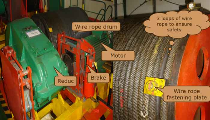
Crane trolley
The lifting mechanism diagram of crane trolley is shown above.:
- Installed on the bridge frame, it is composed of a lifting mechanism, a trolley running mechanism and a lifting trolley frame.
- Lifting mechanism: realize the lifting of goods;
- Trolley running mechanism: drive the lifting trolley to run horizontally and horizontally along the track on the bridge frame;
- Trolley frame: supports the entire trolley and bears the load.
The settings of the main and auxiliary hooks of the lifting trolley:
- When the lifting capacity is less than 10t, only one set of lifting mechanism and one hook are provided;
- When the lifting capacity is >10t, two sets of lifting mechanisms are provided:
- The main lifting mechanism with large lifting capacity is the main hook
- The one with the smaller lifting capacity is the auxiliary lifting mechanism—the auxiliary hook
Generally, the lifting weight of the auxiliary hook is 15% to 20% of the lifting weight of the main hook.
Motors
Motors are divided into: AC motors and DC motors. AC motors are divided into synchronous motors and asynchronous motors. Asynchronous motors are divided into three-phase motors and single-phase motors.
The difference between synchronous motor and asynchronous motor
- 1. The difference between motor synchronization: the speed of synchronous motor is synchronous with the electromagnetic speed, while the speed of asynchronous motor is lower than the electromagnetic speed. No matter the load size of synchronous motor, as long as it does not lose the step, the speed will not change. The speed of asynchronous motor always follows the load size changes with changes.
- 2. Structural differences: Synchronous motors have high precision, but are complex in manufacture, high in cost, and relatively difficult to maintain, while asynchronous motors are slow in response, but easy to install and use, and cheap in price. Therefore, synchronous motors are not as widely used as asynchronous motors.
- 3. Differences in use occasions: Synchronous motors are mostly used in large generators, while asynchronous motors are almost used in motor occasions.
- 4. The main difference The difference between synchronous motors and asynchronous motors lies in whether there is slip (the difference between the magnetic field speed and the rotor speed).
The difference between DC motor and AC motor
- 1. Different types of input power sources: AC motors use AC power (single-phase and three-phase), while DC motors use DC power (constant DC and pulsating DC).
- 2. The structure of the motor is different: DC motors generally have brushes and commutators, while AC motors generally do not. AC motors are more versatile than DC motors! Sparks often appear between the brushes of the DC motor and the commutator, causing the surface of the commutator to oxidize or even insulate.
- 3. Different uses: DC motors are mainly used for power machinery or other equipment with a wide range of speed regulation (requiring smooth speed regulation), such as gantry planers, rolling mills, electric track traction (such as electric locomotives, subways), and AC motors are mainly used It is suitable for power machinery or other equipment with a small speed regulation range, such as general fans, water pumps, machine tools, cranes on construction sites, etc.
Basic structure of crane motors

Asynchronous motors are mainly composed of two parts. The fixed part is called the stator and the rotating part is called the rotor.
Rotor - The rotor consists of the rotor core, rotor windings and shaft. The role of the rotor winding is to induce electromotive force, flow current and generate electromagnetic torque.
The structure type of rotor winding: squirrel cage type and winding type.
According to the structure of the rotor, asynchronous motors are divided into:
- Squirrel-cage asynchronous motor: drives various machinery, such as ventilators, machine tools and transportation machinery, etc.
- Wound rotor asynchronous motor: large starting torque, hoist, water pump and driving.

Squirrel cage rotor
The shape of the rotor winding is like a "squirrel cage". Since the rotor winding of the asynchronous motor does not need to be powered by an external power supply, it can close itself to form a short-circuit winding.

Wound rotor
The wound rotor winding is similar to the stator winding. It is also a three-phase symmetrical winding with insulated wires embedded in the rotor core slot and connected in a star connection.

Conical rotor motor ZD series
Braking features:
- The braking device of the conical rotor motor is composed of a sleeve
- Brake spring on motor rotor, fan brake wheel and end
- Composed of brake rings on the cover.
- Application range: dedicated to hoist lifting
- Manufacturer: Nanjing Special
- Protection level: IP44, IP54
- Insulation class: B class, F class
Motor duty
Indicates the allowable cycle time of the motor under different loads. The working system of the motor is: S1~S10;
The common ones are as follows:
- S3: Intermittent periodic work system
- S4: Intermittent periodic duty with start
- S5: Intermittent periodic duty system with electric braking
- S6: continuous cycle duty system
Duty cycle
Also known as the duty cycle, it refers to the ratio of the equipment to be able to work at full load.
Common are: 25%, 40%, 60% . ( 25%: It means that under full load, it can only work for 25% of the time, that is, it can only work for 25 minutes within 100 minutes, otherwise it will overheat and burn out. )
Insulation class
Cranes are generally Class B or Class F
In electrical equipment such as generators, insulating materials are the weakest link. Insulating materials are particularly susceptible to accelerated aging and damage due to high temperatures. Different insulating materials have different heat resistance properties, and electrical equipment using different insulating materials have different ability to withstand high temperatures. Therefore, general electrical equipment stipulates the maximum working temperature.
Insulation temperature class A class E class B class F class H class C class
Maximum allowable temperature (℃) 105 120 130 155 180 180 or more
Factors affecting the price of the reducer:
- Configuration: the difference between imported and domestic
- Type: helical gear reducer, cycloid reducer, planetary reducer stepless variable speed reducer, worm gear reducer
- Frame size: The larger the frame size, the bigger the reducer
- Motor size and motor type: The reducer must be equipped with a motor. If a special motor is required, the price will be affected, and the price of the reducer with a large motor power will increase accordingly.
- Voltage: 220-480/50, the motor will increase by 10%, 220-480/60 motor will increase by 20%, and the delivery time of voltage 220/60 and 460-480/50 is relatively long
- Protection grade: IP44, IP54, IP55
- Insulation class: B, F, H
- Ambient temperature: -20°C— 40°C
- Special use environment: metallurgy, dust
- Altitude: below 1000 meters
- Special requirements
Reducer
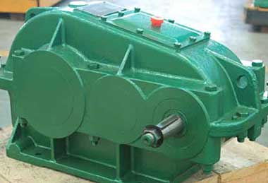
ZQ series cylindrical gear reducer
- Scope of application: used for lifting bridge cranes and running carts
- Classification: Models are divided into: 250, 350, 400,
- There are 8 types of 500, 650, 750, 850, and 1000.
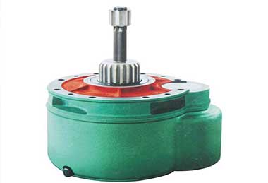
- The reducer is a self-contained part, easy to assemble and disassemble
- Adopt standard modulus cylindrical gear
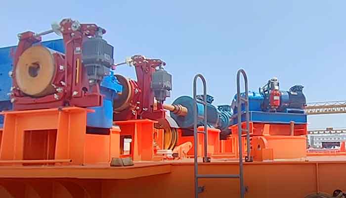
YWZ series electric hydraulic block brake
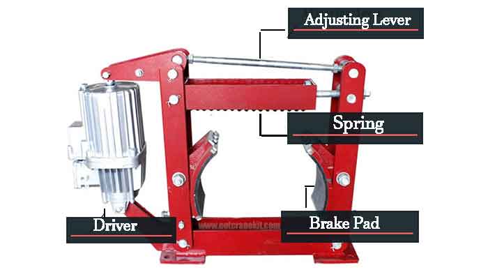
Block brake - Seabury (Germany, specializing in the production of brakes and couplings)
Overload limiter

BCQ series electric hoist weight limiter

BQX series explosion-proof electric hoist load limiter

QCX series lifting weight limiter
Busbar

Seamless busbar(6 square -35 square) - copper conductor
Safe, stable, no interface (except power supply point), small size, convenient installation and economical;
It is suitable for single-girder bridge cranes and cranes with low power consumption. It is recommended that the current intensity is lower than 120A and the running length is within 100 meters;
1. It adopts non-joint installation, which is convenient for transportation and takes up little space for installation.
2. The installation bending radius is small, and the minimum bending radius is 750mm.

Multi pole busbar line (within 200A) - copper conductor
It is suitable for logistics automation production lines and inspection lines with low current and high frequency of use.
1. The casing of the multi-pole trolley type trolley line is made of engineering plastics with high insulation performance. The insulation performance is good, and there is no harm to the maintenance personnel touching the outside of the power transmission conduit.
2. The multi-electrode sliding contact line transmission guide rail has good electrical conductivity, fast heat dissipation, high current density, low impedance value, and small line loss. The brushes are made of metal graphite materials with high electrical conductivity and high wear resistance.

Single pole busbar (200A-2000A)-aluminum alloy conductor
Suitable for most occasions, the first choice for large current and long distance power supply;
Indoor and outdoor use;
- Easy maintenance and low maintenance cost;
- Heat-resistant sheath can be used in high temperature environment;
- Power input point can be provided at any position;

For steel mills - rigid sliding wire
A moving trolley line composed of trapezoidal copper rods and channel steel or a combination of "T" copper bars and channel aluminum
- Rigid body trolley line is composed of trapezoidal copper rod and channel steel or the combination of "T" copper bar and channel aluminum. It is supported by high-strength special insulators to form a moving trolley line that feeds power to various lifting machinery and equipment.
- Product Features - Reliable operation, never power failure
- Structure - Composed of trapezoidal copper bars and channel steel or a combination of "T" copper bars and channel aluminum.

Angle steel sliding wire has the advantages of good wear resistance, high temperature resistance and little wear of carbon brushes, but as a technology more than ten years ago, it also has many shortcomings, such as heavy lifting power consumption, troublesome installation, and difficult operation. Complicated, etc.

C-shaped steel and supporting power supply system
- C-shaped steel supply range: C32, C30, C40, C63
- Cable supply range: 6 square -75 square
- Cooperate with the mobile power supply of bridge gate machine and electric hoist trolley;
- It can work normally in indoor, dusty, dusty, and large temperature difference environments, with low environmental requirements and stable high-speed operation;
- It can be installed with flat cable or round cable;
Hook groups

semi closed hook groups

Full closed crane hook

Double hooks group

Ladle hook group
Types of hooks
- The hook block is mainly composed of a hook and a pulley block. There are generally two types of semi-closed and fully closed hooks.
- According to the shape, it can be divided into single hook and double hook.
- Single hook: easy to manufacture and use, suitable for small tonnage (below 80 tons) cranes;
- Double hooks: symmetrical force, suitable for large-tonnage cranes.
- According to the manufacturing method, it can be divided into forged hooks and sheet hooks (plate hooks).
- Forged hooks: Generally, No. 20 high-quality carbon steel with high strength and good toughness is selected, and then annealed.
- Plate hook: Generally, ordinary carbon steel such as 16Mn or Q235 or low alloy steel is used.
Scrap standards for hooks:
Cast hooks are not allowed; the surface of the hook body is smooth, free of cracks, peeling and any defects that damage the wire rope; the defects on the hook body must not be repaired by welding; the hook should be equipped with a safety device to prevent accidental decoupling.
Hook Group Inquiry Instructions
- tonnage
- Wire rope diameter
- Number of pulleys
- pulley diameter
- Hook opening size
- Whether the material process is required
Types of pulleys
According to the number of wire ropes wound into the drum, it can be divided into 1) single pulley block and 2) double pulley block.

single pulley block

double pulley block.
- Pulley process: casting, rolling, forging.
- Pulley material: cast iron pulley, cast steel pulley, rolled pulley, forged pulley, nylon pulley.
- Cast iron pulleys include gray cast iron pulleys and nodular cast iron pulleys. Gray cast iron pulleys have little wear on wire ropes, but are fragile, and are mostly used for light-duty work; ductile iron pulleys have higher strength and impact toughness than gray cast iron, and are generally used in traditional hoist hook sets.
- Cast steel pulleys, No. 25, No. 35, and No. 45 steel, have high strength and impact toughness, but the workmanship is slightly poor. Due to the hard surface, the wire rope is severely worn. Generally used in hoist trolley hook group.
- Rolled pulleys are generally rolled with No. 45 steel plates, which have the same properties as castings.
- Nylon pulleys are light in weight, wear-resistant, simple in process and low in cost, and can increase the service life of steel wire ropes, but their rigidity is low. Generally used in European hoist hook set.
Safety inspection of the hook:
The inspection cycle shall be determined according to the degree of heavy work and harsh environment, and shall not be less than once a month. Mainly check whether the hook is cracked, deformed and whether the hook nut and anti-loosening device are loose, and check the wear of the bushing, mandrel, small hole, ear hole and its fasteners. The hook assembly part should be overhauled at least once a quarter, and cleaned and lubricated
It should be inspected at least once every six months, and at least once a quarter for frequently used hooks. Before the inspection, the hook body should be cleaned with kerosene, and the dangerous section should be inspected with a 20 times magnifying glass. There must be no cracks, plastic deformation, or loose rivets. For hooks that pass the inspection, the processed surface should be coated with anti-rust oil, the non-processed surface should be coated with anti-rust paint, and marks that are not easy to wear off should be made in the low stress area.
Drum
- The reel is divided into steel plate rolling and seamless steel pipe.
- Steel plate rolling is generally used for hoisting trolleys, φ400-800mm, the maximum can be φ1200mm, and the length is 3-4 meters.
- Seamless steel pipes are generally used for hoists, within φ426mm.
- According to whether there is a rope groove on the surface of the reel: it is divided into smooth surface and spiral groove surface reel.

Smooth reel (feature: with flange, commonly used for multi-layer reels)
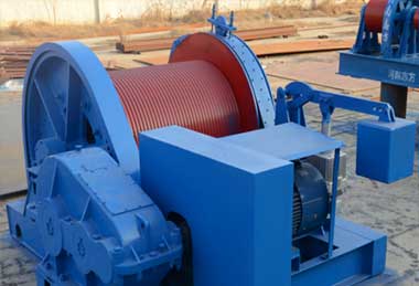
Spiral groove surface reel (feature: no flange, commonly used for single layer reel)
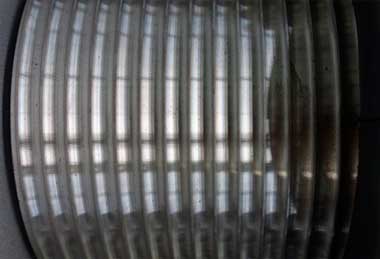
Spiral groove surface reel (feature: no flange, commonly used for single layer reel)
- According to the number of layers of wire rope wound on the reel: it is divided into single-layer winding reel and multi-layer winding reel.
- Most cranes use single-layer winding drums, and multi-layer winding drums are used for cranes with extremely large lifting heights or requiring compact structures (such as truck cranes).
- The roll material is generally cast iron. It can be cast steel or rolled and welded with steel plate when needed.
- The common damaged part is the groove for winding the rope. The reason for the damage is the wear of the wire rope on him; when the deflection angle of the drum and the pulley is too large, the peak groove of the drum will also be worn, and the result will be that the wire rope will be damaged. out of groove.
Wheel set
Wheels are divided into single rim, double rim and no rim wheels. The function of the rim is to guide and prevent the trolley body from derailing.
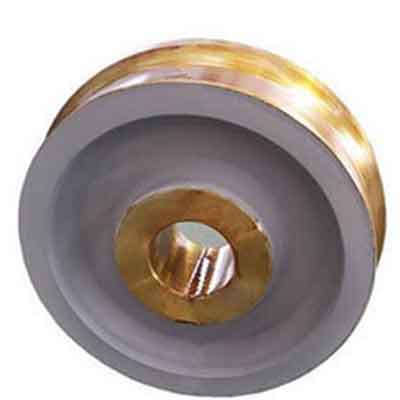
single rim wheel
Generally used for trolley wheels
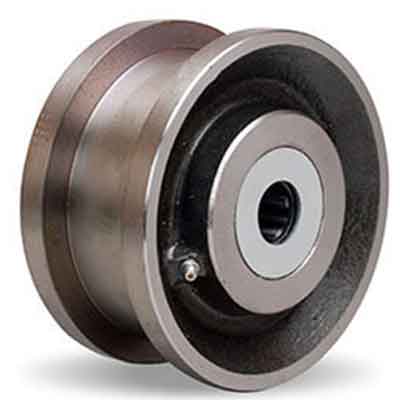
double rim wheels
Wheels for crane trolley ;
Rimless wheels are generally not used on cranes.
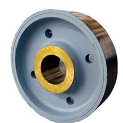
The wheel set is mainly composed of bearing housings and wheels.
Housing material: gray iron, ductile iron, cast steel.
Wheel material: No. 45 steel, ductile iron, 65Mn, 50SiMn, 42CrMo.
Wheel technology: casting, forging.
Scrap standards for wheels:
- When cracks are found on the tread and rim of the wheel, the wheel should be replaced.
- When the wear of the rim of the wheel exceeds 50% of the original thickness, or when the bending deformation of the rim reaches 20% of the original thickness, the wheel should be scrapped.
- During use, if the tread peels off and the scratched area is greater than 2c㎡ and the depth is greater than 3mm, it is allowed to repair, otherwise it should be scrapped. When the tread thickness loss reaches 15% of the original thickness, the wheel is scrapped.
- The wheels are relatively easy to wear and tear, and the frequency of use is different, so they need to be replaced according to the usage conditions.
Production time: 1)10-15 days delivery for standard wheels, 2) 30-45 days for non-standard wheels according to the process and material requirements.
Main Projects
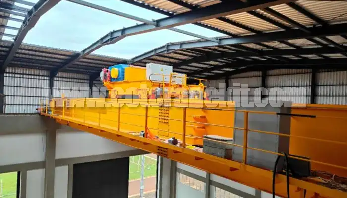
Latest project
150 Ton Overhead Crane Installation Feedback – Paraguay Case
QDX 150 ton overhead crane in action in Paraguay. Installation photos, video, and client feedback show performance, safety, and heavy-lifting efficiency.
Free consultation to Confirm Parameters & Specifications and Get
Latest Crane Price & Crane Rate.
- Types of overhead cranes : _______?
- Optional: Overhead travelling crane, goliath gantry crane,Slewing jib crane, Single girder or double girder crane,small portable crane or kbk crane, etc.
- Capacity of overhead crane: _______?
- Optional: 0.25ton, 0.5 ton, 1 ton, 2 ton, 3ton, 5 ton, 10 ton,15ton, 20ton, 25 ton, 30ton,35ton, up to 550ton, etc.
- Crane span & lifting height : _______?
- Crane travelling length : _____?
- Control of overhead crane:_______?
- Optional: pendant/ remote/cabin control
- Voltage supply of overhead crane:_____?
- Eg,: 380V50/60HZ,3Phase or others,etc.
- Application/usage of crane:_______?
- Eg,: Steel mill, ,injection mold, cement,stone, concrete,granite, general manufacturing, etc.
Just leave a message via the contact form and our hoist and crane engineer will contact you with in 24working hours.
Get In Touch
