Overhead Crane Power Supply System, Electrical System & Maintenance
menu_open
Content Quick Link
Overhead cranes are a widely used lifting equipment in various industrial sector to ensure safety and efficiency. Its frequent use, high workload, vibration, and thus a high failure rate, all have a negative impact on the construction. The electrical system of the overhead travelling bridge crane and the commissioning process, as well as scientific and reasonable construction methods, are critical to ensuring the system's quality. Overhead travelling crane electrical equipment installation and wire laying must strictly adhere to the electrical schematic diagram, wiring diagram, electrical equipment general diagram, and relating standards.

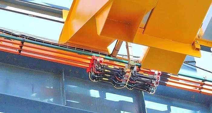
Festoon power supply system for overhead travelling crane
Preparation work before crane installation
Before installing overhead cranes and electrical equipment, it's important to understand the relevant electrical diagrams and technical conditions, as well as the interaction of the components and operating principles, so that problems arising during installation and commissioning can be dealt with quickly. Organize and inspect all electrical equipment and components prior to installation. All electrical equipment and components should be free of flaws, and work should be flexible to avoid the stuck and loosened issue. The drawings must be followed in terms of electrical equipment and components, standards, contact closure sequence, etc.
1.Motor
To begin, inspect the coupling for general appearance, roll the coupling to see if the rotor is rolling flexibly, and test the insulation resistance with a megohm meter. It can be utilized if the stator is more than 1.5 megohm and the rotor is more than 0.8 megohm; otherwise, it must be dried. The drying process can be used in the oven or passed through a low-voltage short-circuit current.
2. Solenoid
If the moving part is loose, skewed, or stuck during installation, it should be removed from the moving part, and the magnet should not come into contact with rust or other contaminants. When using a magnet, there should be no open space between the magnet and the surface it is touching; if adjustments are required, the available space should be eliminated.
3. Linkage operating table or manipulator
The combined surface's contacts should be line touch, with a pressure of about 10 to 17 Newton applied according to the contact size, and the nut adjusted by a compression taut spring. The wire screws must be tightened, and the touch must be exceptional. The gear should be visible and the controlling handle should be flexible.
4. Resistor
The resistor's wiring must be connected appropriately according to the instructions. If the engine is discovered to be insufficiently powerful, the control handle will not be able to raise the rated load or start the big or small automobile in the normal position. The first thing to look for is a problem with the resistor wire. The resistor employed in the organization of double motor drive should be correctly selected and adjusted. For motors closer to the operating room or with "-" slip tolerance, a resistor with a higher resistance value should be utilized.
Resistor installation
Resistors with four boxes and those with fewer than four boxes can be stacked directly. The resistors above four boxes should be put on the resistor frame at an 80mm interval, with a heat insulation plate in the middle to decrease the temperature rise of the uppermost resistor.
The location of the resistor rack should allow for easy access and repair of resistor components while also allowing for heat dissipation. The distance between the resistor element and the wall and floor should be no less than 150 mm, and the channel in front of the rack should be no less than 600 mm.
If necessary, the upper end of the shelf can be added to the pull plate, and one end of the pull plate can be welded to the steel structure. Resistors should be placed parallel to the main beam, and the resistor frame should be solidly installed. Try to lap on the large tension bars of the walking platform to cut the chatter generated by the crane operation.
Maintenance box and control box installation
For a thorough inspection, the maintenance box and control box should be placed before the components and electrical wiring. The toucher interrupter cover and auxiliary contacts, in particular, should not be damaged. The resistance of the line insulation should meet the criteria of the relevant standards. Examine whether the time relay's action corresponds to the rectification value specified in the product's factory technical papers.
Time relay calibration value for the lifting control box: 1SJ for 0.6 seconds, 2SJ for 0.2 seconds, 3SJ for 0.6 seconds, 4SJ for 0.3 seconds. The channel in front of the control must be at least 600 mm wide. The manipulation box should be solid and dependable, and the screen surface should not deviate more than 5 degrees from the straight surface during crane operation.
limit switches Installation
The limit switch is a crucial component that ensures no serious equipment or personnel mishaps occur during crane operation. It should be thoroughly verified before the switch is flexible and trustworthy. After installation, each adjustment should be adjusted one by one. The distance between the large and small car limit switches and the collision rule should be set suitably; if it is too close, the switch will be damaged, and the effect will be lost. The hoisting mechanism's two limit switches should be set individually. The heavy hammer type limit switch should be detached first when the hook reaches the limit height, whereas the rotary type limit switch can be disconnected at a higher position, but the limit height should not be exceeded at this time.
Crand conductor devices
The conductive slide wire's operating surface must be lubricated and clean, and the insulator of the huge car conductor must be in good condition, free of fractures, and securely fastened to the conductive frame. When the conductor is not tightly pressed on the conductive sliding line, such as when the spark operation is bad, the explanation could be that the conductor and conductive sliding line touch is not tight or that the working surface is dirty, or both.
In order to ensure safety, the operation room is usually located on the opposite side of the trolley conductive slide, but if necessary, on the same side, a protective net maintenance should be added.
Crane Trolley cable conductive device
Operating temperature of overhead travelling crane ranges from -25 to 45 degrees Celsius; the cable is CFR type marine rubber insulated neoprene sheathed flexible cable; the highest temperature exceeds 50 degrees Celsius; the cable is CEFR type marine ethylene propylene rubber insulated heat-resistant neoprene sheathed flexible cable. The cable has a YHD type rubber insulated cold resistance rubber sheathed cable when the lowest temperature is -25°C.
The cable should be straightened first, then torque removed, and then arranged on the knotted clip, cable trolley, and dragging trolley in the sequence specified in the figure.
Adjust the orientation of the cable trailer, so that the length of each section of the cable is consistent and adhere to a certain degree of Chi, sagging angle adhere to about 120 °, adjusted, with the cable clamp will be firmly fixed to the cable end clamps and dragging carriage, and then push the trolley to the limit of one end of the operating room, adjust the cable, so that the length of each section of the cable is consistent and adhere to a certain degree of Chi, sagging angle adhere to about 120.The cable is adjusted such that the overhang length of each portion of the cable is roughly the same, and the cable is clamped tightly on the cable carriage.Every 500 to 700 mm, the cable is braided and secured with iron.
Safety grounding
Consider the safety grounding issue after the wire and wire pipe have been placed. To avoid unintentional electrocution, all charged parts of the shell should be reliably grounded. Trolley rails are not welded to the main beam, thus welding grounding is required, and the lighting transformer should be grounded in the low-voltage side, as per the plans.
The grounding wire should be galvanized flat iron with a cross section of at least 75 square millimeters, bare copper wire with a cross section of at least 10 square millimeters, or galvanized round steel with a cross section of at least 30 square millimeters. The grounding connection between the operating room and the crane body should be 410 mm galvanized flat iron with at least two connections. Grounding wire selection welding fastened, or select the equipment on the grounding screw (galvanized), the junction should be free of rust spots, and the grounding wire should be painted black.The grounding resistance between any location on the crane and the power supply's neutral point should not exceed 4 ohms. A fuse shall be installed on the crane or at the start of the power supply slidewire, with the fusible piece's rated current equal to 0.63 times the crane's or power supply slidewire's maximum current.


Article by Bella ,who has been in the hoist and crane field since 2016. Bella provides overhead crane & gantry crane consultation services for clients who need a customized overhead travelling crane solution.Contact her to get free consultation.