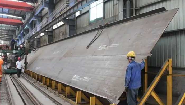
Overhead Crane Manufacturing Procedures | Bridge Crane Manufacturer
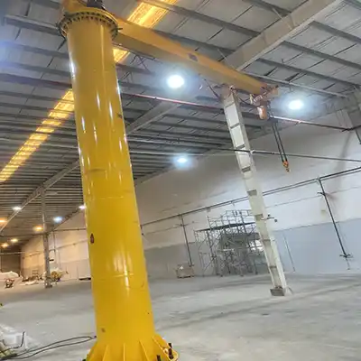
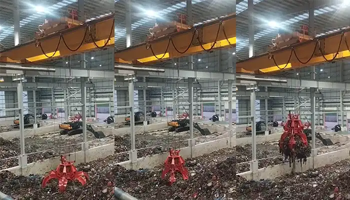
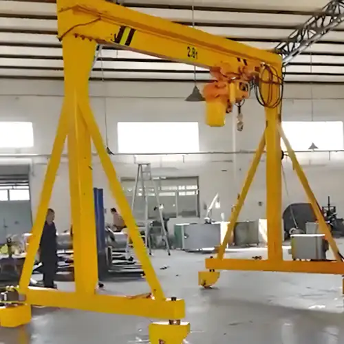
With independent crane design, research, manufacturing, and processing capabilities, we are capable of manufacturing main types of bridge overheadcranes,gantry cranes, jib cranes and processed industrial cranes, etc. Our hoists and cranesare widely used for industries, such as,the metallurgy, hydraulic, power, chemical, paper, shipbuilding, aviation, spaceflight, ports, and other, etc.
Main types of hoist and cranes manufactured
A variety of specialized lifting equipment is available. Typically, the single/double girder overhead crane, single girder /double girder gantry crane, port crane, metallurgy crane, hydraulic crane, workstation crane, freestanding jib cranes, etc. Besides, the standard overhead cranes or general use overhead cranes, the specially designed overhead cranes are available, such as, low clearance bridge crane, explosion-proof crane, container loading crane, ship-building crane, tyre type container loading crane, rail type container loading crane,etc.
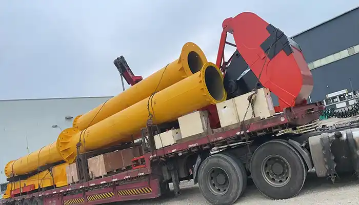
The entire manufacturing process of an overhead crane, includes theraw material inspectionto finished product commissioning.It includes the following major production processes: Semi-finished product manufacturing, machining, heat treatment, assembly, inspection, testing, painting, and other major production processes; as well as packaging, transportation, and other auxiliary processes.
A factory, or a number of factories are take part involvedin theproduct's production process. Besides, thelarge-scale structural components, certain machining components made in-house, and some parts from outside co-processing and manufacturing facilities.
Now the basic process of making an overhead crane are presented for your reference and at the same time,hope you may have a preliminary understanding of our hoist and crane equipment.
The Bridge Crane is made of metal structure, which are mainly consisted of themain beams, end beams, platform and ladder rails, small trolley frame, etc., machined parts, purchasedparts such as,bearings, fasteners, standard parts, etc.), and outsourcing manufactured parts, which refers tothe commission units processing components such as,the hook, etc.
Overhead Crane Processing Chart
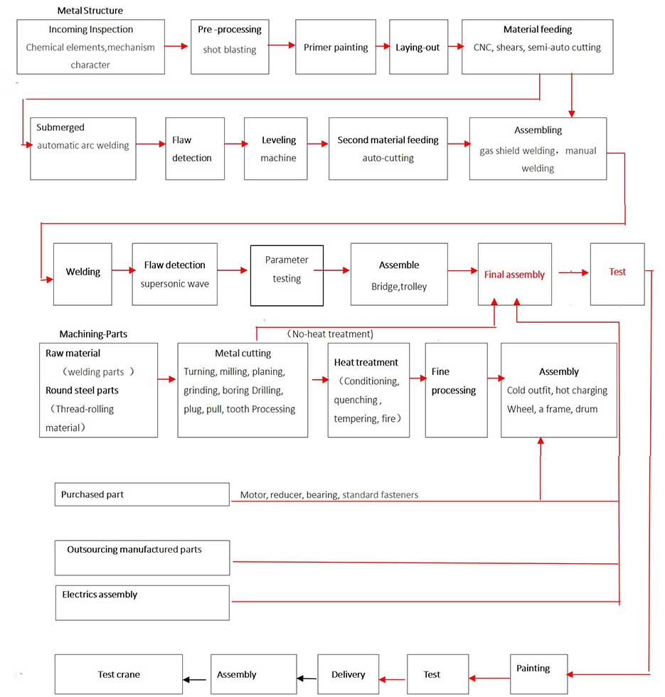
Part 1: Production process for structural parts:
Inspection of the incoming material:
This refers to the quality inspection department to confirm if the arriving materials, such as steel and welding supplies, have certifications and confirming that they are producedin compliance with the company's and national standards. If necessary, recheck and carry out random examination. Random samples will be used to examine the chemical composition and mechanical strength to determine whether they meet company requirements and national standards.
1 Steel
Table 1 Commonly used steel
Steel | Strength grade σs (MPa) (yield point) | Mark |
Universal carbon structural steel | 185-235(the thicker the plate, the smaller the σs) | Q235A Q235AF Q235B Q235BF 20 |
Lmproved carbon structural steel | 315-355 (GB/T699) | 35 45 |
Low-alloy structural steel | 275-345(GB/T1591-1994) | Q345A Q345B |
Steel mark: Q-yield point of steel; 235- yield point strength, unit (MPa); A、B、C、D-quality grade; F— boiling steel (method of deoxidation) b— semi-deoxidized steel Z—killed steel(can be omitted)TZ—special killed steel (can be omitted).
45(35)—carbon content(in ten thousand)
2. Welding material
2.1 Model and specification of welding rod
- Welding rod model (Carbon steel, welding rod)
- E4303 (J422) E4316 (J426) E5003 (J502) E5015 (J507) E5016 (J506)
- Take E5016 as an example, describe meaning of each letter and figure: (E--welding nod, 50- min. tensile strength of deposited metal is 500MPa, 1--suitable location for welding nod: 0,1 means it's suitable for all positions (horizontal, vertical, upward and side-wards), 6- type of the cover.
Features:
- E4303, E5003 slag with good fluidity, removal of slag layer is easy, electric arc is stable, moderate depth of fusion, less splash, weld ripples in good order, suitable for welding on all positions, mainly used for welding of important low-carbon steel structure.
- E4316, E5016 arc are stable, process performance is general and suitable for welding on all positions. Deposited metal of such welding nod has good crack resistance and mechanical property, mainly used for welding of important low-carbon steel structure, and also for welding of low-carbon steel structure that has similar strength.
- Specification of welding nod: φ2.5-φ5
2.2 Model and specification of welding wire
Model of welding wire:
- Automatic submerged-arc welding wire: H08A H08MnA H08Mn2Si H10Mn2 (Original Code).
- Gas Shielded Welding: solid wire: ER50-6 ER49-1 (ER—welding wire, 50— min. tensile strength of deposited metal is 500MPa, 6—code of chemical composition of welding wire)
- EF flux-cored wire
- Specification of welding wire:1.2,φ2.0,φ3.0,φ3.2,φ4.0,
Pretreatment of steel surface:
Before cutting the steel, the surface of important parts is shot or ball blasted to GB8923 standard degree Sa2.5. Anticorrosive primer should be painted right away after the rust is removed.
Pre-treatment equipment:
- Production line for unwinding, leveling, and shearing. (TDT44-10X2200)
- QXY3000 pretreatment (shot blast, paint, and drying in a single line).
- Shot blasting can be used to treat steel plates no wider than 2000 mm by 200 mm or structures no larger than 1800 mm by 1200 mm.
3. Primer painting
To prevent surface corrosion, primer spray will be painted right after after shot blasting.
3.1 Different paints will be utilized depending on the environment, and different primers will be used on the underside of various final coats.(see table two).
Table 2 Painting for overhead cranes
Operating environment | Application environment | Coating thickness(μm) | Recommended paint varieties | |
Primer thickness | Total thickness | |||
General environment | Products used in inland area | 25-35 | 75-105 |
|
Coastal and highly corrosive areas | With salt-fog in coastal areas, industrial atmosphere with corrosion | 50-100 | 150-220 |
|
Hot environment | Products used in hot environment | 25-50 | 50-85 |
|
Strong corrosive environment | Products used in tide and humid conditions for a long time | 60-195 | 230-270 |
|
Environment with oil | parts contact with oil or box with oil medium | 25-50 | 80-160 |
|
Crane painting (including type of paint, color, quantity, thickness of primer and finish coat, etc.) will be made according to contract.
4. Laying-out: mark the shape and processing lines on plate with sample plate,
handrail or diagram.
5. Plate-cutting:
5.1 Cutting method: CNC cutting, semi-automatic cutting, shearing and sawing.
The processing department will select the best cutting technique, make a procedure card, and input the program and number.
5.2 Scope of application for each cutting method:
CNC cutting: complex-shaped plates, such as gusset plates and other specific pieces. Semi-automatic cutting: large parts, edge is in straight line. For instance, use a semi-automatic machine to cut the main girder web plate after connecting it.
5.3 Cutting Equipment
Table 3 Equipment for overhead crane steel raw material cutting
Equipment name | Equipment model | Cutting scale (L×W) | Cutting thickness | Remark |
Digital cutting machine | AG-600 | 50000×6000mm | 6-180mm | |
Digital cutting machine | MESSER OMNIMAT-LK | 50000×6000mm | 6-180mm | |
Semi-auto cutting machine | CG1-30 | 5-40mm | ||
Plate shears | QC121-20X3200 | 3200(width) | 20 | |
Q11-16X2500 | 2500(width) | 16 | ||
Q11-8X2500 | 2500(width) | 8 | ||
Q11-4X2000 | 2000(width) | 4 | ||
Vertical metal band sawing machine | G4265 |
6.Plate connection:
Some parts (such as web plate of main girder) will be connected by several plates. Plates will be connected according to the size, mark, and process requirements. The weld will be bevel cut with a semi-automatic cutter before being treated with automatic submerged-arc welding.
7.Flaw detection:
Because of the importance of the butt weld seam, the grade will be no less than II regulated in GB3323 when detected by ray, and no less than I regulated in JB1152 when detected by ultrasonic. Re-weld after cleaning unqualified parts shaved by carbon arc gouging.
X-ray detector model TF-3125
8. Leveling: level the plate after connecting.
Method: (1)Mechanical leveling: equipment: roller plate leveler W43Q-32X2500 , (2)flame straightening , (3)manual correction
9.Secondary mark, cutting:
Draw cutting lines (marking off) according to the required shape and size and then cut them with a semi-automatic cutting machine after connecting, detecting, and leveling.
10. Assembly
After everything is ready, let's begin assembling all of the plates and materials into a frame. Manual or gas shield welding, positioned welding, whose sew differ based on plate thickness, in the range of 10-60mm. The distance between two welding points is 100-300mm. Tack welding must be done with extreme caution.
As an example, consider the main girder assembly procedure:
- Build a platform: assemble it on the platform, with a flatness of no more than 1 / 1000.
- Place the web plate on the platform and weld the longitudinal reinforcement angle, which is usually double-staggered intermittent welding.
- The cover plate will be tiled on the platform, and the rib and web plate positions will be marked.
- Weld the ribs in accordance with the dot line on the plate, using manual and CO2 spot welding.
- Weld main and aux web plate on cover plate which will be "π" shape beam.
- Weld seams inside, (ribs, web and cover plate); (gas-welding), then paint antirust primer;
- After marking on platform, put “n” shape girder on lower plate; weld seams inside;
- Weld four main seams (automatic submerged-arc welding) and other seams (gas protection welding).
- Correction, limitation. Generally VSR will be used for large components, camber of main girder shall be 0.9-1.4S/1000 (S stands for span).
11. Flaw detection, test
Ultrasonic waves are used to test the welding crack. According to the GB/T12469 standard, the four long welding crack must have a defect grade of II. Structure size and camber must be consistent with the planning drawing.
12. Assembly (assemblage)
Assemblage refers to the process of assembling each component in accordance with the specifications. When connecting the main girder and end carriage to the bridge, ensure that the distance between the centers of the two tracks and the length tolerance of the bridge diagonal line meet the requirements. Assemble the LT and CT mechanisms.
Part 2: Production process of machining parts
1. Rough parts: They primarily consist of cast steel (ZG270-500, ZG340-640, etc.), iron casting (HT, QT), welding (steel plate and welding components), and round steel parts (saw-cut).
2 . Machining: Machining refers to the use of various machine operations (including milling, planing, grinding, boring, drilling, insertion, etc.) to transform mechanical components into ones that are suitable for use.
2.1 Processing equipment
Table 4 Processing equipment for overhead crane manufacturing
No. | Equipment model | Equipment model | Main techanical specifications |
1 | Engine lathe | CA6140 | φ400(max slewing diameter) |
CW6163(CW6263) | φ630(max slewing diameter) | ||
CW6180(CW6280) | φ800(max slewing diameter) | ||
CW61100 | φ1000(max slewing diameter) | ||
CW61125 | φ1250(max slewing diameter) | ||
CW61160 | φ1600(max slewing diameter) | ||
2 | CNC lathe | CKA63135B | φ630×1350 |
CY—K40 | φ400×1000 | ||
CK61315 | φ2500×8000 | ||
CK61200 | φ1200×6000 | ||
3 | Vertical lathe | CA5112EX10/5 | φ1250 |
CA5116E | φ1600 | ||
4 | Milling machine | X6132C | |
X5040 | |||
X5042AF | |||
5 | Edge milling machine | XB-12 | 50×12000 |
6 | Vertical boring and milling process center | VXH718 | |
7 | Planing machine | BY60100C(shaping machine) | |
B2010A(planing machine) | 1000 | ||
8 | Slotting machine | B5032A | |
B5052A | |||
9 | Boring mill (Floor mounted boring and milling machine) | T6920A/160X50 | Main shaftφ200, level shift 16000 |
TT16 | |||
T6110B | |||
TX61130A/1 | |||
TX6113D | |||
10 | Drilling machine | Z3032C | |
Z3050X16/1 | |||
Z3063X20 | |||
Z3080X25 | |||
11 | Grinding machine | M1332C(circular grinding machine) | φ320×1500 |
M1450B(universal circular grinding machine) | φ500×1500 | ||
M7130(plane grinding) | |||
12 | Gear cutting machine | Y3180H | |
YT5180(gear shaper) | |||
Y54A(gear shaper) | |||
13 | Others | spline miller | |
universal cutter and tool grinder | |||
specialized purpose machine |
2.2 Types of commonly used machined parts:
- Round steel parts: general shaft parts use round steel.
- Casting (steel casting, iron casting), forgings, steel plates to be cut, metal structural parts, etc.
2.3 Mechanical processing introduction of our company
- 1. For machined parts, the process department will first make a schedule (drawing number, name, and quantity) with machinery parts based on the drawing and route. The process department will decide whether to use a special or standard machining process based on the complexity of the parts.
- 2. Machining flow process: The mechanical processing center will set up a schedule (fix technical process), prepare roughs in accordance with the machining part schedule, and distribute to each machine tool. Work according to the technical process; for parts that require treatment (such as thermal refining), fine machining will be performed after heat treatment.
- It should be noted that parts must be checked after each process and can only proceed to the next procedure if they are qualified. Only after they have been qualified can they be stored or transferred to other workshops.
- 3. Machining processing and assembly: Assembly will be done by each term and machining center who will be in charge of assembly of wheel, trolley, drum, pulley, and so on. During this process, the bearing cone will be assembled using an induction heating apparatus, while the outer ring press will be assembled using a compression machine.
Part 3: Assembly of electric; assembled by electrician.
Part 4:Bought out item: Items will be purchased in accordance with the configuration table provided by the designing department and the schedule provided by the process department (mostly including the motor, reducer, bearing, standard fastener, electrics, and other standard parts). Assembly each component in accordance with the drawing.
Part 5: Cooperation part: Some components will be designed by us and produced by another company. This includes rough parts like cast steel, iron casting, forgings, and general spare parts. They will be checked and inspected when come to our working site.
Hooks, pulleys, components of drums, cast steel, iron casting, forgings, etc. are examples of collaboration parts at the moment.
Part 6: Final assembly: Each component should be put together in accordance with the general drawing, such as the hoisting mechanism on the trolley, the pulley and support stand, the traveling mechanism, etc. For easier shipment, some components must be disassembled. These components must then be trial-erected at the manufacturer's site, where a welding positioning block must be placed in the proper area to position the second assembly. Determine which component will be installed at the user's site based on the individual conditions. Some pieces, such as stairs and handrails, will be installed at the installation site of the user's according to the specific conditions.
Part 7: Inspection: After final assembly, the quality inspection department will thoroughly examine it in accordance with the relevant standards and technical specifications, and if it passes, it will issue an ex-work certificate.
Part 8: Paint: Depending on the contract or working environment, choose a unique paint (color, type). The process department shall prepare the color and type of the painting (type, color, quantity, thickness of primary and finish coats, etc.) in accordance with the contract requirements. Table 2 shows paint used in various environments.
Part 9: Paint inspection: When the painting is finished, check to see if the film thickness meets the requirements and there are no defects such as sag or crinkle.
Part 10: Delivery: transport the product to user.
Part 11: Site erection
Part 12: Acceptance
In the above, it is the main processing procedures of overhead cranes just for your reference. As for processed cranes and custom cranes, special processes will be added or changed. If you have any need of overhead crane, please feel free to contact us. Custom overhead crane are manufactured based on your lifting conditions and requirements. Contact us today to get your crane design drawing.
