
Crane Beam & Crane Design
menu_open
Content Quick Link
Crane-Beams or Crane Girders are unique among structural components in that, unlike conventional beams and Plate-Girders, they must endure strong lateral stresses caused by the crane gantry's movement along the track and the trolley's cross-movement across the crane gantry. They also have to withstand the longitudinal forces created by the crane gantry's acceleration, travel, and braking on the track.
As a result of the crane-wheels eccentric loading on the crane-rail, the crane-girder must be constructed to resist bending, web buckling, and top-flange deformation. To counteract lateral forces, deeper crane-girder sections (more than 400 mm) will require a tie-back or continuous surge-girder to secure the top-flange to the building column.
The crane-girder is stiffened against deformation by web and flange stiffeners positioned at intervals along its length (See Crane-Girder Stiffening), while lateral support is provided by 'Tie-Backs' or 'Surge-Girders' that restrain the girder top-flange against the building column (See Crane-Girder Top-Flange Restraint).

Crane-girders can be simply supported, semi-continuous, or continuous, however simply-supported crane-girders are the de-facto norm due to the difficulties in design of the latter, as well as the difficulty of erection and alignment.
With the girder ends bearing on the column cap-plate or Corbel, the simply-supported girder essentially spans from column to column. (For further information, see Crane Columns)
Typical crane Girder Sections
The following are examples of crane-girder sections:
1.Standard Hot-Rolled Beams, which are commonly utilized for short-span, lightly loaded applications.
2.A regular hot-rolled section with an inverted channel cap can be used to support the top-flange and resist lateral loading from the crane-wheels in slightly heavier applications.

Though the channel-cap efficiently stiffens the top flange, it is of limited use in terms of lateral rigidity.
1.Symmetrical Plate-Girders are utilized for heavy-duty wide-span applications and can be customized to fit any need.
2.In very-heavy-duty applications, monosymmetric Plate-Girders often have a broader and thicker top-flange.
Crane-Girder Support
Crane girders are typically supported by seating the bottom flange of the girder onto the supporting column.
The crane-girder may be seated onto a bracket, or corbel, attached to a single-leg portal column for light-duty applications; however, the capacity of such connections is limited by the strong moments induced into the column.
A stepped portal column is frequently employed to expand the capacity of portal-frame structures, with the crane-girder seating onto the cap-plate above the column's flange. The roof rafter is supported by the decreased section.
Twin-leg columns are used for heavy-duty cranes, and the crane girder is supported by seating onto the crane-column leg's cap-plate. The roof-leg is attached to the building column and extends to support the rafter or truss on the roof.


There are a variety of ways to support the crane-girder onto the column-cap, all of which are decided by design considerations; nevertheless, for the sake of this exercise, we will look at three choices that together form a reasonably common cross section.
The girder ends are fastened to the column cap-plate with four bolts in each example (or to the top-flange of the cantilevered corbel).
When one or both girders are loaded, the ends of the girders move longitudinally, causing the distance between the abutting girders to increase and decrease. Because the crane girders must be allowed to rotate in this manner, the horizontal load path's longitudinal continuity is maintained through the connection.
The crane-girder can be fastened directly to the column cap-plate for light-duty applications, with bearing stiffeners oriented to the supporting column flanges to provide effective weight transmission into the column. The column cap-plate helps to maintain horizontal continuity.
The crane-girder may seat into a bearing-pad for Medium/Heavy-Duty applications to help reduce any eccentric loading onto the column, which must be minimal enough to guarantee the girder is easily supported. At the girder ends, bearing stiffeners are positioned, and a central stiffener is located in the column web.
This stiffener should be continuous, which means a slot in the column web should be cut and the stiffener inserted and welded to improve the column's bearing capacity.
The girder ends may sit on a nib-plate that fits inside the bolt-group and is not directly bolted through the girder bottom-flange for heavy-duty applications. Horizontal continuity is done with a continuity-plate that must be thin enough to avoid bending resistance while still allowing longitudinal forces to move in a continuous line.


Girder Stiffening
This stiffener should be continuous, which means a slot in the column web should be cut and the stiffener inserted and welded to improve the column's bearing capacity.
The girder ends may sit on a nib-plate that fits inside the bolt-group and is not directly bolted through the girder bottom-flange for heavy-duty applications. Horizontal continuity is done with a continuity-plate that must be thin enough to avoid bending resistance while still allowing longitudinal forces to move in a continuous line.
The crane girder's top-flange must be reinforced and constrained to alleviate these concerns. The crane girder is stiffened by a combination of flange and web stiffeners positioned at intervals along its length, while lateral stresses are restrained by Tie-Backs or Surge-Girders, which tie the crane girder to the building structure. (Restraining possibilities for Crane-Girder are covered later in this article.)


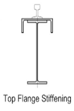
Top-Flange Stiffeners
When using a normal hot-rolled beam section, the top flange is commonly reinforced by an inverted channel section welded to the beam's top flange. This technique will offer the top-flange more support and provide some resistance to lateral loading from the crane wheels. However, because the channel is of minimal utility in supplying the requisite lateral rigidity for heavy-duty cranes, this structure only applies to light/medium applications.
The inverted channel, on the other hand, lends itself to easy Tie-Back choices, which we'll go into later in this post.
Welded Plate-Girders
Plate-girders present a unique set of challenges:
The weld between the top-flange and the web is particularly sensitive to fatigue because to the repetitive cyclic pressure on the top-flange; as a result, fillet-welds are not recommended due to the difficulties in establishing full flange to web contact.
Welds with full penetration into the groove should be used.
Although this requirement does not apply to the bottom-flange, it is common practice to use groove-welds in both the top and bottom flanges during the manufacturing stage to avoid them being crossed-over later.
When looking into intermediate flange stiffeners, the same concerns must be taken into account. The top of the stiffener can be welded to the underside of the top-flange or not, but whatever option is chosen, the stiffener must be fitted for full bearing to avoid weld cracking due to fatigue. When a stiffener is 'fitted,' it indicates that the top of the stiffener is cut true and square to ensure full contact between the mating sides.
For the same reason, shallow 'Snipes' at the Flange/Web intersection should be avoided; instead, a 'engineered' cope should be employed – see illustration below.
When intermediate, or'stub' stiffeners are required, they should be put one or two between the transverse stiffeners or spaced equally to the pitch of the rail clips.
Transverse Web Stiffeners
The Transverse Web-Stiffeners run the length of the girder at regular intervals.
The transverse stiffener should not be welded to the bottom-flange in crane girders that are simply supported (at each end). Fillet- Welds that run parallel to the tension flange are prone to failure due to fatigue. A space of not more than - 4 x the girder flange thickness should be maintained between the stiffeners and the girder flange. The tops of the stiffeners may or may not be welded to the top-underside. flange's They should be placed to the underside of the flange for full-bearing if they are not welded.

For light to medium-duty applications, the longitudinal welds on the girder web can be intermediate Fillet-Welds, but for heavy-duty applications, they should be continuous Fillet-Welds returned at the top and bottom.
The same fundamental rules apply to continuous crane-girders, with the exception that the stiffener should be placed to the underside of the top-flange rather than welded. The bottom-flange stiffener may or may not be welded to it.
To avoid fatigue cracks in the web, the weld access hole, or cope, should be deep enough (as for intermediate flange stiffeners).
Bearing Stiffeners
Bearing stiffeners are attached to the underside of the bottom flange and placed at the ends of the crane girder for full bearing. The stiffeners should be placed at the point of bearing in the case of a continuous girder.
Fillet-Welds can be utilized for stiffeners up to 12 mm thick, however full bearing onto the flange may be difficult to obtain with Fillet-Welds. Prepared welds with at least 90% penetration should be utilized for stiffeners bigger than 12 mm thick.
Except for continuous girders, where stiffeners should only be fitted to the underside of the top-flange and Fillet-Welded, the stiffener should extend and be fitted to the underside of the top-flange and be Fillet-Welded.
When girder ends abut over a column, the squareness of the girder ends must be within tight tolerances. Rail-joints are common at this location, and any misalignment or variances in level will cause a discontinuity, affecting wheel wear and rail fastening.
Bearing stiffeners should be placed directly above the bearing point. This may be in-line with the flanges of the supporting column placed outside of the attaching bolts for light to medium duty applications.
Bearing stiffeners are frequently installed at the girder ends for heavy duty applications, enabling enough space for the vertical Fillet-Weld. In such cases, a column stiffener should be welded onto the column to ensure the column's full bearing capability. This stiffener should be continuous, with a slot cut into the column web to accommodate the stiffener's installation. (For more information, see Crane-Girder Support.)
To ensure that the girder is simply supported, the fastening bolts are situated outside of the bearing stiffeners.


Main type of crane girder designs
One of the most significant crane sections is the main overhead crane girder or overhead crane beam design, which supports the trolley or hoist. Crane main girders are categorised as truss girders, box girders, single girders, and double girders, and many other types of structures. Single girder, double girder, triple girder, box girder, truss grider, and other girder designs are available. Please do not hesitate to contact us if you require crane girder design.

Single girder : A single crane girder or crane beam that runs above or below the runway/end carriages /end trucks.

Double girder : Consists of 2 bridge beams or girders on top of the crane runway/end trucks/ end carriages.

Top running crane girder: Eelectric overhead crane or shorted as EOT crane is mounted to the top of the runways.

Under running (under hung)crane girder : Electric overhead crane with the end trucks attached and supported to the flanges on the bottom of the runway beams.
Article by Bella ,who has been in the hoist and crane field since 2016. Bella provides overhead crane & gantry crane consultation services for clients who need a customized overhead travelling crane solution.Contact her to get free consultation.