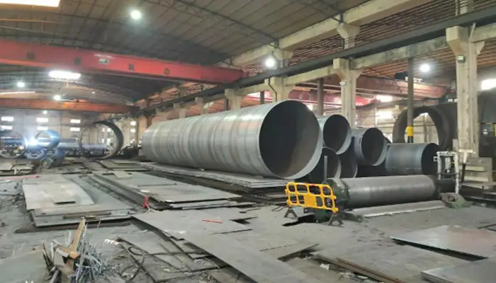
How to Plan Overhead Crane Layout for a Silo Factory
Content Quick Link
Silo Manufacturing Overhead Crane Layout Planning: A Buyer's Technical Guide
In a silo factory, where you place overhead cranes depends on how the work is done, what needs to be lifted, and how materials move through the workshop. Each workshop handles different materials, different component sizes, and different lifting working duty or frequency, so the crane capacity, type, and quantity in each bay should follow the actual production flow. Get this wrong and you either overspend on capacity you don't need or fight bottlenecks for the life of the plant.
Most silo factories are laid out in stages: raw material storage, plate cutting, rolling and shell forming, shell welding and assembly, hopper and roof fabrication, and finally assembly and dispatch. Smaller plants often combine several of these under one crane runway. Larger plants usually separate them into dedicated bays, each with its own crane sized for that stage.Here's what each area typically needs, with the numbers buyers actually ask about.
Raw Material Storage and Steel Handling
This is where steel plates, coils, profiles, and structural sections come in, get unloaded, stored, and fed to the cutting lines. The crane here does the heaviest and most varied lifting in the plant, so it needs wide coverage and the right below-the-hook gear for each material type.
| Material | Typical Size | Weight | Usual Lifting Attachment |
|---|---|---|---|
| Steel plates | 2–8 m × 1.5–2.5 m | 0.5–3 t | Plate clamps, magnetic lifters, or lifting beams |
| Steel coils | Ø 1–2 m × 1–1.8 m wide | 2–10 t | Coil C-hook or coil grab |
| Steel profiles | 6–12 m lengths | 0.5–5 t | Lifting beam with multiple hook points |
| Structural sections | Project-specific | 1–8 t | Standard hooks with slings or spreader beams |
What to specify:
- Capacity: 5–15 t is the normal range. For coils, size the crane on the heaviest coil plus the C-hook weight — C-hooks typically add 5–10% to the coil weight.
- Crane type: Single girder works up to about 10 t and 25 m span. Go double girder if you're lifting heavier, spanning wider, or running frequent heavy cycles.
- Duty class: FEM 1Am / ISO M4–M5 for moderate use; FEM 2m / ISO M6 if the storage bay runs multiple shifts.
- Span and height: 15–30 m span, 8–12 m lifting height, depending on rack height and how trucks unload.
- Speeds: Long travel 20–40 m/min, cross travel 10–20 m/min keeps retrieval quick without load swing.
- Quantity: One or two cranes per runway. If the storage area runs past about 100 m, or you're moving more than 500 t a month, plan on two.
One practical point: VFD on travel and hoisting isn't a luxury here. It cuts load swing noticeably when you're pulling plates off racks at speed, and positioning lands within about ±5 mm.
Steel Plate Cutting and Preparation
Plates move from storage to CNC, plasma, laser, or shear cutting, then on to rolling. The crane's job is precise loading and unloading of machine beds without nicking plate edges or knocking the machine out of alignment.
| Item | Typical Size | Weight | Usual Attachment |
|---|---|---|---|
| Full plates | 6–8 m × 1.5–2.5 m | 0.5–3 t | Plate clamps or vacuum lifters |
| Cut sections | Project-specific | 0.2–2 t | Magnetic lifters or plate clamps |
| Plate bundles | Project-specific | 1–5 t | Lifting beam with multiple sling points |
| Prepared components | Project-specific | 0.5–3 t | Standard hooks with slings |
What to specify:
- Capacity: 3–5 t covers most cutting bays. If you're using vacuum lifters on full plates, add 15–20% for the lifter weight.
- Crane type: Single girder handles most of this. Move to double girder only if capacity, span, or duty pushes past single-girder limits.
- Duty class: FEM 1Am / ISO M4 for intermittent cutting; FEM 2m / ISO M5 for multi-shift production.
- Span and height: 12–25 m span, 6–10 m height — enough to clear cutting tables and machine enclosures.
- Positioning: Aim for ±3 mm with VFD on hoist and cross travel. Acceleration around 0.1–0.3 m/s² keeps plates from swinging into the machine.
- Quantity: One per bay normally; two if you run multiple cutting lines or the bay runs past about 80 m.
Long, thin plates are the trap here. If the length-to-thickness ratio is over about 100:1, use a multi-point lifting beam. A single hook will bow the plate and you'll be straightening it before it ever reaches the rolls.
Plate Rolling and Cylindrical Shell Fabrication
This is one of the two most demanding crane areas in silo production. Flat plates go into the rolls and come out as curved sections or full cylindrical shells, and the crane moves them to welding. Shells are flexible, awkward, and easy to deform, so load control matters as much as raw capacity.
| Item | Typical Size | Weight | Usual Attachment |
|---|---|---|---|
| Plates before rolling | 6–12 m long | 1–5 t | Plate clamps or lifting beams |
| Rolled sections | Project-specific | 1–8 t | Spreader beams or custom lifting frames |
| Cylindrical shells | Ø 3–8 m × 1.5–3 m | 2–10 t+ | Shell lifting frame, multiple contact points |
| Large shells | Ø 8–12 m × 2–3 m | 10–25 t (project-specific) | Engineered spreader with adjustable sling points |
A rough weight check before you talk to a crane supplier: shell weight (kg) ≈ π × diameter (m) × height (m) × plate thickness (mm) × 7.85 × 1.1, where the 1.1 accounts for stiffeners and attachments. Plate thickness in silo work typically runs 4–20 mm.
What to specify:
- Capacity: 5–20 t normally. For shells over Ø 8 m, plan on 20–30 t to cover shell weight plus the lifting frame (frames usually add 10–15%).
- Crane type: Single or double girder depending on weight, span, and duty. Above 15 t or past 25 m span, double girder is the sensible choice.
- Duty class: FEM 2m / ISO M5–M6, since rolling and shell handling run continuously.
- Span and height: 18–30 m span, 10–15 m height. Rolling machines sit 3–5 m tall, and stacked shells add another 3 m — keep at least 1 m of clearance above the tallest point.
- Speeds: Hoisting 0.5–5 m/min, travel 10–30 m/min. Slow and steady beats fast and swinging when you're moving a 10 t shell.
- Quantity: One or two per bay. Two makes sense when plate feeding and shell removal happen at the same time, or the bay runs past about 100 m.
Two things buyers frequently miss. First, a crane with a main and auxiliary hoist pays for itself here — the main hoist handles shells, the auxiliary handles plates and tooling without dragging the big hook around. Second, the lifting frame needs to hold shell roundness to within about 1% of diameter; beyond that you're fighting ovality at the weld station.
Shell Welding and Assembly
This bay handles the biggest and heaviest pieces in the plant. Shells get lifted, aligned, and held for circumferential and longitudinal welding, and often several sections get stacked into larger assemblies. Alignment happens in millimeters, so this is where crane precision really earns its keep.
| Item | Typical Size | Weight | Usual Attachment |
|---|---|---|---|
| Small shells | Ø 3–6 m × 1.5–3 m | 2–8 t | Shell lifting frame or spreader beam |
| Medium shells | Ø 6–10 m × 2–3 m | 5–15 t | Spreader beam, 4-point lift |
| Large shells | Ø 10–12 m+ | 10–25 t+ | Custom frame, 6–8 point lift |
| Reinforced assemblies | Project-specific | 10–35 t+ | Multi-point beam with load monitoring |
These are indicative ranges — always confirm from the component drawings, and check whether the center of gravity sits off-center, because on large assemblies it often does.
What to specify:
- Capacity: 10–30 t is the working range, with 30–50 t for heavier assemblies. Size on max shell weight plus frame weight plus a 10% margin.
- Crane type: Double girder, full stop. Single girder isn't the right tool above 20 t or for precision alignment work.
- Duty class: FEM 2m–3m / ISO M6–M7 for continuous multi-shift assembly.
- Span and height: 20–35 m span, 12–18 m height, with at least 2 m clearance above the tallest assembly.
- Positioning: ±1 mm with VFD on hoist and travel. This is the number that decides whether your welders fight the fit-up or not.
- Lifting points: 4–8 points to spread the load and stop the shell going oval. The frame design should account for shell stiffness, not just weight.
- Quantity: One or two per bay; more in very long bays. Where two cranes share a runway, anti-collision is mandatory, not optional.
If two cranes work the same runway, put laser or radar anti-collision on both with adjustable warning and stop zones, tied into the crane controls. And a load display with data logging is worth having — it gives you a record for QA and tells you when a lift is drifting toward the limit.
Hopper, Cone, and Roof Fabrication
Hoppers, discharge cones, roof panels, trusses, and support frames are usually built in their own bay before moving to final assembly. Smaller plants fold this into general steel fabrication. The challenge here isn't weight — it's shape variety.
| Item | Typical Size | Weight | Usual Attachment |
|---|---|---|---|
| Hopper sections | Ø 2–6 m | 2–10 t | Custom lifting frame or spreader beam |
| Discharge cones | Project-specific | 2–10 t | Frame with adjustable sling points |
| Roof panels | 3–8 m long | 0.5–3 t | Lifting beam, multiple hook points |
| Trusses and frames | 3–12 m long | 1–8 t | Spreader beam or lifting frame |
| Support structures | Project-specific | 1–8 t | Standard hooks with slings |
What to specify:
- Capacity: 5–15 t. Hoppers over Ø 4 m usually want 10–15 t to cover the hopper plus frame.
- Crane type: Single girder up to about 10 t and 20 m span; double girder beyond that.
- Duty class: FEM 1Am–2m / ISO M4–M5.
- Span and height: 15–25 m span, 8–12 m height.
- Quantity: One per bay; two for bays past about 80 m or where roof and hopper work run separately.
Cones and hoppers often have offset centers of gravity, so a rotating hook or a frame with adjustable sling points saves a lot of fiddling during fit-up. For roof structures, use 4–6 lifting points — two-point lifts twist trusses and you'll be reworking them.
Final Assembly, Inspection, and Dispatch
The last bay handles finished sections, large assemblies, inspection, temporary storage, and truck loading. Cranes here need the plant's highest capacity and enough height and reach to load out cleanly.
| Item | Typical Size | Weight | Usual Attachment |
|---|---|---|---|
| Finished cylindrical sections | Ø 3–12 m+ | 5–25 t | Engineered spreader or shell frame |
| Large silo assemblies | Project-specific | 10–35 t+ | Multi-point beam with load monitoring |
| Finished hoppers | Project-specific | 2–15 t | Custom lifting frame |
| Support assemblies | Project-specific | 5–20 t | Spreader beam or lifting frame |
What to specify:
- Capacity: 10–50 t or higher, sized on the heaviest finished component plus attachment plus 10%.
- Crane type: Double girder for heavy work; single girder is fine for lighter dispatch operations.
- Duty class: FEM 2m–3m / ISO M5–M7 for multi-shift dispatch.
- Span and height: 20–35 m span, 12–18 m height. Truck decks sit 1.5–2 m up, and you still need 2 m of clearance over the tallest component during loading.
- Positioning: ±5 mm with VFD travel is realistic and sufficient for loading.
- Quantity: One or two per bay; more in plants past about 150 m of bay length. Anti-collision again wherever cranes share a runway.
Two extras that pay off in dispatch: a weighing system to verify finished weight before the truck leaves, and a runway that actually reaches the loading dock rather than stopping short of it. A crane with main and auxiliary hoists also helps — big hook for the silo section, small hook for rigging and loading gear.
Typical Crane Layout Across the Plant
| Workshop | Main Loads | Capacity | Crane Type | No. of Cranes | Duty (FEM/ISO) | Span (m) | Lift Height (m) |
|---|---|---|---|---|---|---|---|
| Raw material storage | Plates, coils, profiles | 5–15 t | Single or double | 1–2 | 1Am–2m / M4–M5 | 15–30 | 8–12 |
| Plate cutting | Full plates, cut sections | 3–5 t | Single | 1–2 | 1Am–2m / M4–M5 | 12–25 | 6–10 |
| Rolling and shell fab | Rolled plates, shells | 5–20 t | Single or double | 1–2 | 2m / M5–M6 | 18–30 | 10–15 |
| Shell welding and assembly | Large shells, assemblies | 10–30 t+ | Double | 1–2 | 2m–3m / M6–M7 | 20–35 | 12–18 |
| Hopper and roof fab | Cones, panels, trusses | 5–15 t | Single or double | 1–2 | 1Am–2m / M4–M5 | 15–25 | 8–12 |
| Final assembly and dispatch | Finished sections, heavy structures | 10–50 t+ | Double | 1–2 | 2m–3m / M5–M7 | 20–35 | 12–18 |
Treat these as starting points for a layout discussion, not a specification. Real quantities depend on bay dimensions, runway length, throughput, how materials actually move, and where crane operating zones overlap.
Sharing Workshops and Crane Bays
Not every process needs its own building. Whether operations can share a runway comes down to layout, volume, component size, and how often lifts happen.
| Arrangement | Operations That Can Share | What to Watch |
|---|---|---|
| Raw material + preparation | Storage, sorting, cutting prep | Keep storage and machine-loading zones separate; span must reach both |
| Cutting + rolling | Cutting, prep, rolling | Span must reach cutting tables and rolls; height must clear roll housings |
| Shell fabrication | Rolling, positioning, weld prep | Check shell size against coverage and weld clearance; VFD for positioning; anti-collision if two cranes |
| Shell assembly | Alignment, welding, assembly | Needs higher capacity, 4–8 point lifting, load monitoring, ±1 mm positioning |
| Structural fabrication | Hoppers, cones, roofs, frames | Flexible attachments matter more than capacity |
| Final assembly + dispatch | Finished handling, inspection, loading | Check truck access and clearance; runway must reach the dock |
Small to mid-size plants (under roughly 5,000 t/year): combine storage with plate prep, run rolling and lighter shell work in one bay, and keep a dedicated area for heavy assembly and finished handling. A single runway with two or three cranes at different capacities — say 5 t, 15 t, and 30 t — can serve several stages if the runway is long enough and the span covers everything.
Large plants (over roughly 10,000 t/year): separate bays usually win, because the capacity, attachments, and duty requirements diverge too much to share. Splitting light fabrication (5–10 t cranes) from heavy assembly (30–50 t cranes) onto separate runways also cuts capital cost, since you're not dragging a 50 t crane through cutting work.
How Many Cranes Does the Plant Actually Need?
Factory size alone doesn't answer this. What matters is how many lifts happen at once and how material moves between stages. Work through these:
- Runway length. One crane per 60–80 m of runway is a reasonable starting point for moderate lifting frequency.
- Heaviest load. If shell assembly needs 30–50 t, give it a dedicated crane rather than over-specifying the light-duty cranes.
- Throughput. Above roughly 10,000 t/year, plan one crane per 500–800 t of monthly material movement to avoid queues.
- Lift frequency. Past about 20 lifts an hour, dedicated cranes per line beat sharing one.
- Coverage. One crane can serve several stations if span and runway reach all loading points, weld stations, and storage zones.
- Simultaneous work. Plate feeding and shell removal in the same bay at the same time means two cranes, or one very patient operator.
- Interference. Multiple cranes on one runway need defined operating zones and anti-collision. Sort this out at design stage, not after installation.
- Expansion. Adding a crane to an existing runway later is far cheaper than extending the building. Size the runway for tomorrow.
- Redundancy. On critical lines, a second hoist or a spare crane keeps production running through maintenance.
Where two cranes share a runway, the runway structure must be designed for their combined wheel loads, including dynamic factors. This is a structural engineering question, not just a crane question.
A warning worth repeating: two cranes on one runway do not add up to double capacity. Tandem lifting needs engineered load-sharing, synchronized hoisting, approved procedures, and a runway designed for the concentrated loads. Talk to the crane maker and a structural engineer before anyone plans a tandem lift.
Features That Matter When Configuring the Cranes
Beyond capacity and type, these are the details that separate a crane that works well for fifteen years from one that fights you daily.
- Double girder where it counts. Above 15 t, or for precision shell work, double girder gives you rigidity, more hook height, and better hook approach. It also lets you run main and auxiliary hoists, which is genuinely useful in rolling and dispatch bays.
- VFD on all motions. Controlled acceleration of 0.1–0.5 m/s² gives you ±1–5 mm positioning and much less load swing. It also cuts brake and gearbox wear, which shows up in your maintenance budget. Put VFD on hoist, long travel, and cross travel.
- Attachments matched to the load. Plate clamps or vacuum lifters for plate, C-hooks or grabs for coils, spreader beams and shell frames for cylinders, custom frames for hoppers, multi-point beams for structural assemblies. Give the crane maker your max load dimensions and centers of gravity — attachment design depends on both.
- Radio remote with proportional control. The operator can stand where they can actually see the load. Frequency-hopping radios hold up better in plants with a lot of electrical noise. Dual or walk-along stations help in long bays.
- Overload protection with a real margin. Load-cell based, audible and visual alarm, automatic hoist cut-off at 110% of rated capacity. For critical lifts, add load display and data logging for QA records.
- Anti-collision on shared runways. Laser or radar with adjustable warning and stop zones, integrated with crane controls so it stops the crane, not just beeps at the operator.
- Duty class chosen honestly. Silo work typically lands in FEM 1Am–3m / ISO M4–M7. Over-specifying raises the price; under-specifying shortens life and raises maintenance. Base it on lifts per hour, shifts per week, and load spectrum.
- Environmental protection. IP55 or better on electricals for dusty plants. Corrosion protection for humid or coastal sites. Weatherproof enclosures and motor heaters if any part of the crane sits outdoors.
- Height and hook approach. Set lifting height from the tallest component plus the highest workstation, and check hook approach (500–800 mm from runway centerline minimum) reaches every station. Low buildings may need a low-headroom crane design.
- Span and runway length. Span from building width and required coverage. Runway should run at least 5 m past the last workstation at each end for parking and maintenance access.
- Wheel loads and runway compatibility. Give the crane maker your rail type, runway beam size, and column spacing so wheel loads match the structure. Runway design must include dynamic and impact factors.
- Power supply and control voltage. Confirm voltage, frequency, and phases up front. 24V or 48V DC control is standard for safety. A busbar system cuts cable wear and improves reliability on long runways.
- Maintenance access. Walkways, platforms, and ladders to the hoist and gearboxes. A girder walkway and hoist platform turn a two-hour job into a twenty-minute one.
- Noise. 80–85 dB(A) at 1 m is a reasonable target; low-noise hoists and gearboxes are available where it matters.
- Documentation and certification. Operation and maintenance manuals, spare parts lists, wiring diagrams, test certificates. For safety-critical work, third-party inspection to CE, ISO, or local standards.
The Workflow, End to End
Raw material storage → plate cutting → rolling → shell fabrication → shell welding and assembly → hopper and roof fabrication → final assembly → inspection and dispatch.
Each stage either gets its own crane or shares coverage with the stage next to it. Which one is right depends on your layout, max load dimensions and weights, lift frequency, and how material actually travels between stations.
| Stage | Capacity | Crane Type | Key Attachment | What Matters Most |
|---|---|---|---|---|
| Raw material storage | 5–15 t | Single or double | Coil C-hook, plate clamps | Wide coverage, VFD travel |
| Plate cutting | 3–5 t | Single | Vacuum or magnetic lifters | ±3 mm positioning |
| Rolling | 5–20 t | Single or double | Spreader beams, shell frames | Controlled speed, load balance |
| Shell welding and assembly | 10–30 t+ | Double | Multi-point lifting beams | ±1 mm alignment, anti-collision |
| Hopper and roof fab | 5–15 t | Single or double | Custom lifting frames | Flexible handling, multiple points |
| Final assembly and dispatch | 10–50 t+ | Double | Spreader beams, lifting frames | Capacity, truck loading clearance |
What to Send the Crane Manufacturer
The quality of your crane proposal depends almost entirely on the information you provide. Hand over these and you'll get a specification that fits, not a generic quote:
- Workshop layout drawings — plan and elevation, column spacing, runway beam locations, workstation positions.
- Runway details — length, span between rail centerlines, rail type and size, runway beam size and material, column spacing.
- Maximum component weights — per bay, including attachment weight, with component drawings where available.
- Component dimensions — max length, width, height, diameter, and centers of gravity where offset.
- Lifting heights — max lift height including clearance over workstations, racks, and trucks.
- Number of bays — and whether they share a runway or have separate ones.
- Lift frequency and duty cycle — lifts per hour, hours per day, shifts per week. This drives duty class.
- Power supply — voltage, frequency, phases, control voltage preference, busbar or cable.
- Site conditions — indoor or outdoor, temperature range, humidity, dust, corrosive atmosphere, any special requirements.
- Control preferences — radio, pendant, or cabin; station locations; dual or walk-along stations.
- Safety and certification — local regulations, third-party inspection, CE/ISO/FEM/CMAA requirements.
- Expansion plans — any future increases in capacity, component size, or building extension.
- Budget and timeline — budget range, required delivery date, and installation schedule constraints.
With this in hand, the manufacturer can recommend crane quantity, capacity, type, and configuration for the whole plant — properly sized, safe, and built to last.
Quick Reference: Selection Criteria
| Criterion | What Drives It | Typical Silo Plant Values |
|---|---|---|
| Capacity | Max component + attachment + 10% | 3–50 t by bay |
| Crane type | Duty, capacity, precision needs | Single (cutting, hopper); double (assembly, dispatch) |
| Duty class | Lift frequency, hours, load spectrum | FEM 1Am–3m / ISO M4–M7 |
| Span | Building width minus runway clearance | 12–35 m |
| Lifting height | Tallest component + clearance + hook approach | 6–18 m |
| Hoisting speed | Precision needs, lift frequency | 0.5–8 m/min, VFD |
| Travel speed | Runway length, positioning accuracy | 10–40 m/min long; 10–20 m/min cross |
| Control | Operator visibility, layout | Radio remote preferred; pendant or cabin as alternatives |
| Attachments | Component geometry and material | Plate clamps, C-hooks, spreader beams, shell frames |
| Safety features | Number of cranes per runway, criticality | Overload protection, anti-collision, limit switches, VFD braking |
| Environmental protection | Dust, humidity, temperature | IP55+, corrosion protection where needed |
Use this as a starting framework. Final specifications should come from a qualified crane engineer working from your actual layout and load data.
Send Us An Inquiiry to Get Your Made to Order Overhead Crane Solution for Your Factory
Before requesting an overhead crane layout proposal, prepare the following information:
- Factory building width: ____ m (Example: 30 m)
- Factory building length: ____ m (Example: 100 m)
- Building height: ____ m (Example: 12 m)
- Number of production bays: ____ (Example: 5)
- Maximum lifting capacity: ____ ton (Example: 20 ton)
- Required lifting height: ____ m (Example: 10 m)
- Crane span: ____ m (Example: 28 m)
- Runway length: ____ m (Example: 90 m)
- Working duty: ____ (Example: ISO A5)
- Power supply: ____ (Example: 400 V, 50 Hz, 3-phase)
- Existing building drawings: ____ (Available / Not available)
- Future expansion requirements: ____ (Example: Additional shell assembly bay)
Providing a factory floor plan, equipment layout, and component drawings will help the engineering team evaluate crane coverage and quantities more accurately.
FAQs About Overhead Crane Layout for Silo Factories
Answers to common questions about overhead crane layout for silo factories, covering crane quantity, commonly used capacities, multi-bay coverage, single vs. double girder selection, shell handling capacity, workshop arrangement, shared runways, building information, planning timing, and future upgrades.
How many overhead cranes does a silo manufacturing factory need?
A small factory may need approximately 2–3 cranes, a medium factory 4–6 cranes, and a large factory 6–10 or more. The actual number depends on production volume, workshop layout, lifting frequency, and crane coverage.
What is the most commonly used overhead crane capacity for silo manufacturing?
Crane capacities around 5–20 ton are useful for many general silo fabrication operations. A 5 ton crane may handle steel plates and light components, while 10–20 ton cranes may be used for rolled shell sections and heavier fabrication. Larger assembly operations may require 30–50 ton or higher capacities.
Can one overhead crane serve multiple production bays?
Yes. One crane can serve multiple workstations if they are within its travel coverage, the loads are within its rated capacity, and the lifting operations do not conflict.
Should a silo factory use single-girder or double-girder overhead cranes?
Single-girder cranes are commonly considered for light and medium material handling. Double-girder cranes are generally preferred for heavier loads, larger spans, higher lifting requirements, and demanding working duties. Final selection depends on the complete design conditions.
What crane capacity is suitable for cylindrical silo shell handling?
A 10–20 ton crane may be suitable for many medium-sized shell sections. Larger or reinforced sections may require 20–30 ton or higher cranes. The actual capacity must include the lifting frame and other suspended equipment.
How should overhead cranes be arranged in a large fabrication workshop?
Divide the workshop into production bays and arrange crane runways according to material flow. Dedicated cranes may be appropriate for raw material handling, shell fabrication, heavy assembly, and dispatch.
Can two overhead cranes operate on the same runway?
Yes, if the runway structure, crane arrangement, controls, and operating zones are designed for multiple cranes. Anti-collision protection may also be required.
What building information is required before installing an overhead crane?
The crane manufacturer needs the building width, length, height, crane span, runway length, rail elevation, available headroom, and structural drawings. Wheel loads and supporting structure capacity must also be checked.
Should crane layout be planned before factory construction?
Yes. Planning during the building design stage helps coordinate crane span, runway beams, building columns, lifting height, and material flow. This can reduce structural modifications and installation costs later.
How can a factory prepare for future crane capacity upgrades?
Consider future component weights, production expansion, runway design loads, building structure, and available headroom during the initial planning stage. Any future crane upgrade must be checked against the runway and building structure.
Get an Overhead Crane Layout Recommendation for Your Silo Factory
Planning a new silo manufacturing factory or upgrading an existing workshop? Yuantai Crane can help evaluate the required silo manufacturing overhead crane capacities, quantities, configurations, and runway arrangements.
To start your project evaluation, provide:
- Factory layout or building drawings.
- Production process and workshop bay arrangement.
- Maximum component weights and dimensions.
- Required lifting heights and crane spans.
- Expected production volume and lifting frequency.
Our engineering team can review your requirements and recommend an overhead crane arrangement for your silo manufacturing facility.

Article by Bella ,who has been in the hoist and crane field since 2016. Bella provides overhead crane & gantry crane consultation services for clients who need a customized overhead travelling crane solution.Contact her to get free consultation.
Yuantai Cranes
Overhead Crane Manufacturer with CE, ISO, SGS, CNEX Certificates.
- Main Specifications - Capacity: 0.5–550 tons | Span: up to 40m | Speed: 0.8–12 m/min | Duty: A3–A7 | Power: 380–690V, 50/60Hz | Control: pendant/remote/cabin
- Full engineering: FEA/PLC/VFD + in-house build + global delivery + on-site support, for workshops, factories, EPC contractors, industrial projects, etc.
- Support: design, manufacturing, testing, service – end-to-end, customized lifting solutions worldwide.
How to Get an Accurate Crane Price for Your Application?
Tips: Copy the spec list, fill in your details, and paste it into the form on the right/ down-below for a quick price.
- Crane type:_____ . (e.g., overhead crane, gantry crane, jib crane)
- Max weight to lift:_____ tons. (e.g., 2t, 5t, 10t, 20t, 50t)
- Lifting height:_____ m. (How high does the hook need to reach?
- Workshop width (span):_____ m . (Distance between the two crane rails)
- Travel distance:_____ m . (How long does the crane need to move along the runway?)
- Control type:_____. (Pendant / remote / cabin Control)
- Power supply:_____. (Local voltage & frequency – e.g., 380V, 50Hz, 3-phase)
- What will it be used for?_____ (e.g., steel fabrication, concrete products, mold handling, general manufacturing, etc.)
- Any special requirements?_____ (e.g., extreme temperature, dusty or explosive environment, special paint color, etc.)
Just leave a message via the contact form and our hoist and crane engineer will contact you with in 24working hours.
Get Your Custom Quote–Quick & Easy
Fill in what you know. Skip what you don't – we'll help.Any question will be reply with 24 working hours