Crane Girder Design and Selection for Overhead & Gantry Cranes
Content Quick Link
Crane girder design is a critical part of an overhead crane or gantry crane system. The main girder supports the hoist trolley and transfers lifting loads to the crane's end carriages and supporting structure. Its design must account for the rated lifting capacity, crane span, trolley weight, dynamic forces, braking loads, and repeated operating cycles.
Selecting the right crane girder involves more than choosing a steel beam based on lifting capacity. Girder geometry, steel grade, structural stiffness, allowable deflection, fatigue resistance, lifting height, and operating conditions all affect crane performance, service life, and overall project cost. An unsuitable configuration can lead to excessive deflection, increased wheel loads, restricted hook travel, premature structural fatigue, or unnecessary manufacturing and installation expenses.
This guide explains how to evaluate crane girder types, structural materials, span requirements, deflection limits, and industrial applications. Whether you are specifying a single-girder overhead crane for a workshop, a double-girder bridge crane for heavy manufacturing, or a long-span gantry crane for infrastructure projects, understanding these factors will help you define the right structural configuration for your application.
Crane Main Girder vs. Building Runway Beam: What Is the Difference?
The crane main girder and the building runway beam serve different structural functions.
- Crane main girder: Forms the bridge structure of an overhead crane or the upper load-carrying structure of a gantry crane. It supports the hoist trolley and transfers the resulting forces through the end carriages or supporting legs.
- Building runway beam: Supports the crane's travel rails and carries the loads transmitted by the crane wheels into the building columns or other supporting structures.
Both components must be compatible with the crane's rated capacity, span, wheel loads, operating duty, and applicable design requirements. A suitable crane girder does not automatically mean the existing runway system can support the new crane. Runway beams, columns, connections, foundations, and local load effects may require separate engineering verification.
Quick Guide to Crane Girder Selection
The appropriate girder configuration depends on the complete lifting application rather than a single parameter.
| Selection factor | What buyers should evaluate |
|---|---|
| Rated lifting capacity | Maximum load, auxiliary hoists, lifting attachments, and trolley weight |
| Crane span | Distance between runway rails for an overhead crane, or the relevant support geometry for a gantry crane |
| Girder structure | Rolled I-beam, welded I-section, box girder, or truss girder, depending on the application |
| Duty classification | Operating frequency, load spectrum, lifting cycles, and required service life |
| Structural stiffness | Allowable deflection, vibration, trolley travel, and positioning accuracy |
| Lifting height and headroom | Available building clearance, hoist arrangement, and required hook travel |
| Steel grade | Strength, toughness, weldability, fatigue requirements, and operating temperature |
| Operating environment | Dust, humidity, corrosion, high temperatures, wind exposure, or hazardous atmospheres |
| Project budget | Fabrication, transportation, installation, runway modifications, maintenance, and lifecycle costs |
Where to Start
For a practical selection process, begin with the crane's rated capacity, span, lifting height, and duty class. Then evaluate the available installation space, operating environment, trolley arrangement, and supporting structure. These inputs establish the design conditions for comparing I-beam, box girder, and truss girder configurations.
The following sections examine the engineering factors behind these decisions, including [crane girder types and structural configurations], [I-beam vs. box girder selection], [crane girder deflection requirements], and [steel grade selection for crane girders].
For buyers preparing a quotation request, the most useful starting information is the required lifting capacity, span, lifting height, duty classification, power supply, application, and project location. Existing building or runway drawings are also valuable when available. Providing these details allows a crane manufacturer to assess the appropriate configuration and identify the additional engineering information needed for a reliable proposal.
What Is a Crane Girder?
A crane girder is a primary structural beam that supports the bridge of an overhead crane or the supporting frame of certain gantry cranes. In an overhead crane, the main girder spans the working area and carries the hoist trolley, lifting equipment, and lifted load. Its structural design affects load capacity, deflection, fatigue resistance, lifting height, operational stability, and overall crane cost.
For crane buyers, selecting the right overhead crane girder requires more than matching the rated lifting capacity. The crane span, trolley wheel loads, duty class, operating environment, available headroom, and applicable design standards must also be considered. These factors determine whether a single-girder, double-girder, I-beam, or box-girder configuration is suitable for the project.
It is also important to distinguish the crane bridge girder from the building runway beam. The bridge girder travels with the crane and supports the lifting mechanism, while the runway beam is part of the building or supporting steel structure and carries the crane's wheel loads. Both structures must be checked for compatibility, but they perform different functions.
Main Girder vs. Runway Girder: Structural Roles and Differences
The crane main girder and the runway girder are two separate structural components in a typical overhead crane installation.
| Component | Primary function | Main design considerations |
|---|---|---|
| Crane main girder (crane bridge girder) | Spans across the working area and supports the hoist trolley and lifted load | Rated capacity, span, trolley wheel loads, bending stress, deflection, fatigue, and headroom |
| Runway girder (runway beam) | Supports the crane's end-carriage wheels along the building or dedicated runway structure | Maximum wheel loads, wheel spacing, lateral forces, runway span, deflection, and supporting-column capacity |
| Building columns and supporting structure | Transfers runway loads into the foundations | Vertical and horizontal forces, structural stability, connections, and foundation capacity |
The runway beam must be designed for the actual crane wheel loads and operating forces rather than the rated lifting capacity alone. The main girder and runway system should therefore be evaluated together during project engineering.
How the Main Girder Supports the Hoist, Trolley and Lifted Load
During lifting operations, the main girder carries the weight of the crane structure and the forces transferred by the hoist trolley. The principal loads include:
- Hoist and trolley weight: The dead weight of the trolley, hoist, motors, and associated equipment.
- Lifted load: The rated load suspended from the hook, including the effects required by the applicable design standard.
- Trolley wheel loads: Concentrated forces transferred from the trolley wheels to the girder or trolley rail.
- Dynamic effects: Additional forces associated with lifting, starting, stopping, and changes in operating conditions.
- Horizontal forces: Forces generated by trolley acceleration, braking, skewing, or other movements, as applicable to the crane design.
- Fatigue loading: Repeated stress cycles accumulated over the crane's service life.
The girder must have adequate strength to resist the design loads and sufficient stiffness to control deflection. Excessive deflection can affect trolley movement, load positioning, and operating performance. The required structural checks depend on the crane configuration, duty classification, applicable standards, and project specifications.
Single-Girder vs. Double-Girder Crane Configurations
The number and arrangement of main girders influence the crane's structural design, available lifting height, trolley arrangement, and overall cost.
| Feature | Single-girder overhead crane | Double-girder overhead crane |
|---|---|---|
| Main girder arrangement | One main girder | Two main girders |
| Typical hoist arrangement | Hoist or trolley commonly travels beneath or along the girder, depending on design | Trolley commonly travels on rails mounted on top of the girders |
| Structural configuration | Generally simpler and lighter | Generally heavier and more complex |
| Lifting height | Depends on hoist design, headroom, and installation arrangement | May provide greater hook height for suitable configurations |
| Typical selection considerations | Moderate lifting requirements, building constraints, and economical system design | Higher capacities, demanding duty requirements, specialized trolley arrangements, or greater structural demands |
| Cost considerations | Often lower crane dead weight and initial cost | Higher structural and equipment costs may apply, depending on specifications |
Neither configuration should be selected by capacity alone. Span, duty class, lifting height, wheel loads, service life, and required operating performance must be evaluated before the final girder arrangement is chosen.
Main Girder, End Carriage, Trolley Rail and Runway System
An overhead crane operates as an integrated structural and mechanical system. Understanding the main components helps buyers define the correct scope when requesting a quotation.
- Main girder: The primary bridge beam that supports the trolley and transfers loads to the end carriages.
- End carriages: The assemblies at the ends of the bridge that support the crane travel wheels and connect the bridge to the runway system.
- Trolley rail: The track on which the hoist trolley travels across the bridge. Its position and support arrangement depend on the crane design.
- Hoist trolley: The moving assembly carrying the hoist and lifting mechanism.
- Runway beam: The longitudinal supporting beam along which the complete overhead crane travels.
- Runway rails and wheel assemblies: The interfaces that guide crane travel and transfer wheel forces into the supporting structure.
- Supporting columns and foundations: The building or independent support system that transfers crane loads to the ground.
Suggested visual: Include a labeled overhead crane structural diagram identifying the main girder, end carriages, hoist trolley, trolley rail, runway beam, runway rail, and supporting columns. Use clear labels and ensure the diagram distinguishes the moving crane bridge from the stationary building support structure.
Loads Considered in Crane Girder Design
Crane girder design calculations must account for the load combinations and operating forces specified by the applicable design code. Depending on the crane and installation, the principal considerations include:
- Dead loads: The self-weight of the girder, end carriages, trolley, hoist, rails, and permanently installed equipment.
- Lifted load: The rated load and any required allowance for lifting dynamics or load handling equipment.
- Trolley wheel loads: The concentrated loads transferred through the trolley wheels, including their spacing and positions along the bridge.
- Crane wheel loads: The forces transmitted through the end-carriage wheels to the runway beams and supporting structure.
- Dynamic and impact effects: Forces associated with lifting, crane travel, trolley travel, acceleration, and braking, as required by the relevant standard.
- Horizontal forces: Transverse and longitudinal forces arising from crane operation, skewing, or braking where applicable.
- Fatigue: Repeated loading cycles that can influence the design life of the girder, welds, connections, and other structural details.
- Environmental loads: Wind, temperature, corrosion, dust, or other site-specific conditions where relevant to the installation.
The design should check strength, local and overall stability, deflection, fatigue resistance, connections, and other limit states required by the governing standard. Actual design loads should be calculated from the crane configuration and operating conditions rather than estimated from rated capacity alone.
Key Factors That Determine Crane Girder Design
Overhead crane girder design depends on lifting capacity, span, duty class, structural performance, and operating conditions. Two cranes with the same rated capacity may require different girder designs because of differences in trolley weight, operating frequency, headroom, or installation requirements.
Rated Capacity and Hoist/Trolley Weight
The girder must support the lifted load, hoist and trolley, and other applicable loads. The final design depends on the complete loading conditions, not rated capacity alone.
| Parameter | Information Required |
|---|---|
| Rated capacity | Main hoist capacity and any auxiliary hoist capacity |
| Hoist and trolley | Type, weight, and wheel arrangement |
| Load type | General materials, steel coils, machinery, molds, or specialized loads |
| Operating conditions | Frequent starts and stops, positioning requirements, and load-handling cycle |
Crane Span and Wheelbase
Crane span is the distance between the runway rail centerlines. Wheelbase is the spacing between the crane travel wheels along the end carriage. Both affect structural loading and crane configuration.
| Parameter | Why It Matters |
|---|---|
| Crane span | Influences girder bending, stiffness, and structural weight |
| Wheelbase | Affects wheel-load distribution on the runway |
| Runway arrangement | Determines support conditions and installation geometry |
| Existing building structure | Must be checked for compatibility with the proposed crane |
| Installation clearance | Affects crane dimensions and maintenance access |
For existing facilities, provide runway drawings and available structural assessments so the supporting beams and columns can be checked before the crane design is finalized.
Lifting Height, Headroom and Hook Approach
Lifting height determines the required hook travel, while headroom and hook approach affect how effectively the crane uses the available building space.
| Requirement | What to Check |
|---|---|
| Lifting height | Required hook travel and highest hook position |
| Headroom | Clearance between the runway, hoist, and building obstructions |
| Hook approach | Required access near runway and bridge ends |
| Building clearance | Roof trusses, lighting, pipes, ducts, and other obstructions |
| Hoist configuration | Whether a low-headroom hoist or double-girder arrangement is appropriate |
A higher lifting height does not automatically require a deeper girder. The complete hoist, trolley, and crane arrangement should be evaluated together.
Duty Class, Operating Frequency and Design Life
Crane duty classification reflects how frequently and intensively a crane operates. A maintenance crane used occasionally has different fatigue demands from a production crane handling loads throughout multiple shifts.
| Factor | Information to Provide |
|---|---|
| Operating hours | Hours per shift and number of shifts |
| Lifting cycles | Expected cycles per hour, day, or year |
| Load spectrum | Typical loads and frequency of heavy lifts |
| Service life | Expected operating life and maintenance requirements |
| Classification | Required ISO, FEM, or other applicable classification |
ISO and FEM classifications should not be assumed to be directly interchangeable. Confirm the governing standard and the basis of the supplier's proposed duty classification.
Deflection, Vibration and Positioning Accuracy
Girder deflection is its displacement under load. Excessive deflection or vibration can affect trolley travel, load positioning, and production processes.
| Design Consideration | Why It Matters |
|---|---|
| Deflection limit | Controls structural movement under specified loads |
| Positioning accuracy | Important for machinery, molds, coils, and precision handling |
| Acceleration and braking | Can influence dynamic response and operating smoothness |
| Vibration and alignment | May affect crane travel and specialized applications |
The allowable deflection depends on the applicable design standard, crane arrangement, and project specification. Ask the supplier to provide the calculated deflection and the acceptance criterion used.
Runway Capacity and Maximum Wheel Loads
The existing runway beams, columns, and connections must be capable of supporting the proposed crane's wheel loads and applicable operating forces.
| Information Required | Purpose |
|---|---|
| Maximum and minimum wheel loads | Supports runway structural verification |
| Wheel spacing | Establishes load distribution |
| Runway beam and rail details | Helps assess existing support conditions |
| Column spacing and connections | Supports evaluation of the load path |
| Existing structural assessment | Identifies known limitations or reinforcement needs |
A runway that supports an existing crane may not be suitable for a replacement crane with different wheel loads, wheel spacing, or operating requirements. Have the supporting structure checked by a qualified structural engineer.
Operating Environment
Temperature, corrosion, dust, moisture, and explosion risks can affect the crane's materials, protective coatings, mechanical components, and electrical equipment.
| Operating Condition | Design Considerations |
|---|---|
| High temperature | Heat exposure, component temperature ratings, and required shielding |
| Corrosive environment | Material suitability, coating system, and maintenance |
| Dust and contamination | Protection of moving parts and electrical equipment |
| High humidity or water exposure | Corrosion control and suitable component protection |
| Hazardous atmosphere | Equipment requirements for the specified gas or dust classification |
| Outdoor operation | Applicable wind loads, weather exposure, and corrosion protection |
Identify these conditions before requesting a quotation because they can affect the design, equipment selection, price, and delivery schedule.
Applicable Design Standards and Project Specifications
The governing standards determine the required design checks, material specifications, fabrication controls, inspection, and documentation.
| Requirement | What Buyers Should Confirm |
|---|---|
| Design standards | Applicable crane and structural standards, including the required edition |
| Materials | Required steel grades and material traceability |
| Welding and inspection | Welding procedures, inspection methods, and any required non-destructive testing |
| Engineering documents | Structural calculations and drawings for approval |
| Certification | Required product documentation and third-party inspection |
| Local compliance | Building codes and responsibility for runway verification |
Depending on the project, applicable requirements may reference ISO, FEM, EN, CMAA, or other national or industry standards. These standards are not automatically interchangeable.
Buyer tip: Confirm the required standards and documentation before design approval. Changes made later can require revised calculations, drawings, fabrication, and pricing.
Crane Girder Design: Buyer Checklist
Use this checklist to prepare a complete technical inquiry and help the crane supplier evaluate the main girder and supporting structure.
| Information required | What to provide |
|---|---|
| Rated capacity | Required lifting capacity in ton, including any auxiliary hoist |
| Crane span | Distance between runway rail centerlines |
| Lifting height | Required hook travel and highest hook position |
| Duty class | Required classification or operating profile and load spectrum |
| Travel speed | Crane travel, trolley travel, and hoisting speeds, including any variable-frequency control requirements |
| Load type | Materials handled, load dimensions, lifting attachments, and any special handling conditions |
| Operating hours | Cycles per hour, shifts per day, operating days per year, and expected service life |
| Installation conditions | Indoor or outdoor use, available headroom, building drawings, runway dimensions, and obstructions |
| Operating environment | Temperature, corrosion, dust, humidity, wind exposure, or hazardous-area classification |
| Required standards | Applicable crane design code, structural code, certification, inspection, and documentation requirements |
| Existing runway information | Runway beam drawings, rail details, wheel-load limits, supporting columns, and previous structural assessments |
| Commercial requirements | Target delivery schedule, installation scope, testing, spare parts, and budget constraints |
Before requesting a quotation: Provide the rated capacity, span, lifting height, duty requirements, operating environment, and available runway information at a minimum. If some parameters are not yet known, identify them as preliminary so the engineering team can clarify assumptions before finalizing the design.
Types of Crane Girders: I-Beam, Box Girder and Truss Girder
The main girder supports the hoist or trolley and transfers lifting loads to the crane structure. Common overhead crane beam types include rolled I-beams, rolled H-beams, welded I-section girders, box girders, and truss girders.
The right crane girder depends on lifting capacity, span, duty class, hoist arrangement, headroom, operating environment, and design requirements.
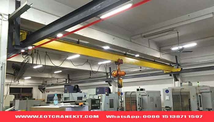
I beam crane
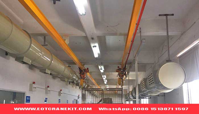
Monorail I beam crane
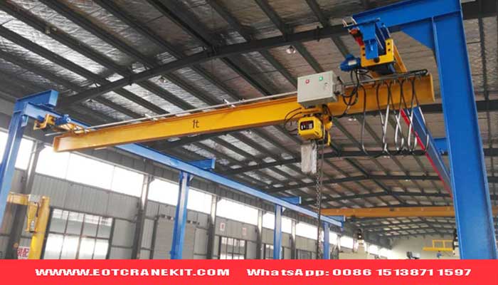
Freestanding i beam overhead crane
Rolled I-Beam and H-Beam Girders
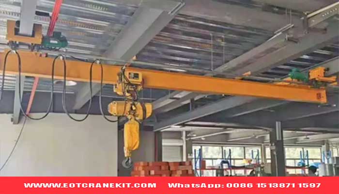
Rolled I-beams and H-beams are standardized steel sections that may suit selected crane beams, monorail systems, and underslung lifting arrangements.
| Feature | Rolled I-Beam | Rolled H-Beam |
|---|---|---|
| Section shape | Relatively narrow flanges in many standard profiles | Generally wider flanges |
| Typical consideration | Suitable section properties and trolley interface | Flange width, local strength, and structural stability |
| Potential advantage | Standardized section and relatively simple procurement | May offer suitable properties for different support arrangements |
| Design checks | Deflection, flange bending, stability, wheel contact, and fatigue | Deflection, local strength, stability, connections, and fatigue |
A standard section should not be selected by lifting capacity alone. Its suitability must be verified for the actual span, loading, support conditions, and trolley or wheel arrangement.
Welded I-Section Girders
A welded I-section girder is fabricated by joining steel plates to form two flanges and a web. Its dimensions can be customized when standard rolled sections do not meet the project's requirements.
| Feature | Engineering Consideration |
|---|---|
| Section dimensions | Web depth and flange sizes can be tailored |
| Material use | Plate dimensions can be optimized for calculated loads |
| Structural checks | Bending, shear, buckling, stability, and deflection |
| Fabrication | Welding quality, dimensional accuracy, and distortion control |
| Fatigue | Weld details and repeated loading require evaluation |
Welded I-section girders can suit project-specific crane structures, provided their strength, stiffness, stability, and fatigue performance meet the applicable requirements.
Box Girders for Overhead and Gantry Cranes
A box girder is typically fabricated from welded steel plates to form a closed section. It is commonly considered for double-girder overhead cranes, heavy-duty cranes, and gantry cranes where the required structural performance justifies its fabrication.
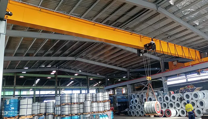
box girder overhead crane for heavy duty applicaiton in the steel mill for steel coil handling
Box girder gantry crane for outdoor applicaiton
| Feature | Engineering Consideration |
|---|---|
| Structural stiffness | Closed sections can provide high torsional stiffness |
| Capacity and span | Section dimensions, plate thickness, and stiffeners must match the design loads |
| Trolley arrangement | Rail position and trolley wheel loads affect the design |
| Fabrication | Welding, alignment, stiffeners, and inspection are important |
| Maintenance | External surfaces are accessible, but internal areas may require dedicated inspection provisions |
A box girder is not automatically required for every high-capacity or long-span crane. Selection should consider structural demands, dead weight, fatigue, manufacturing complexity, and total project cost.
Truss Girders for Selected Long-Span Applications
A truss girder uses interconnected structural members to transfer loads through an engineered framework. It may be suitable for selected long-span gantry cranes and infrastructure projects.
| Potential Advantage | Design Consideration |
|---|---|
| Efficient use of structural members | Member forces and overall stability require analysis |
| Potentially reduced self-weight | Actual weight depends on the complete design |
| Adaptability to large structures | Transport, assembly, and site erection must be planned |
| Open structural arrangement | Wind exposure, corrosion protection, and inspection access require attention |
| Multiple joints and connections | Fatigue, welding, bolting, and maintenance must be considered |
Truss girders are application-dependent options, not automatic replacements for box girders. The choice should be based on structural performance, fabrication, installation, environmental loads, and lifecycle cost.
How Girder Type Relates to Hoist and Trolley Arrangement
The girder must match how the hoist or trolley travels and transfers its loads.
| Crane Arrangement | Key Design Considerations |
|---|---|
| Underslung or under-running crane | Lower-flange strength, wheel contact, support conditions, and clearances |
| Top-running single-girder crane | Rail or trolley interface, local stresses, and structural stability |
| Top-running double-girder crane | Trolley wheel spacing, load distribution, rail alignment, and stability |
| Monorail crane | Beam bending, local flange effects, lateral stability, and support arrangement |
Headroom, hook approach, trolley wheelbase, and runway geometry should be checked together. A structurally adequate girder may still be unsuitable if it cannot provide the required lifting height or trolley travel.
Open-Section vs. Closed-Section Crane Girders
I-beams and welded I-sections are open profiles, while box girders use a closed profile. Their structural behavior and fabrication requirements differ.
| Comparison Factor | Open Sections | Box Girders |
|---|---|---|
| Torsional stiffness | Generally lower than a comparable well-designed closed section | Can provide higher torsional stiffness |
| Fabrication | Rolled sections may require less fabrication | Usually requires plate welding and internal structural details |
| Structural checks | Flange and web behavior, lateral stability, and load application | Plate buckling, stiffeners, welds, and local stability |
| Inspection | Many surfaces are readily accessible | Internal spaces may need dedicated inspection access |
| Selection priority | Confirm strength, stiffness, stability, and fatigue | Confirm that performance benefits justify fabrication and maintenance requirements |
Neither open nor closed sections are best for every crane. The final selection must meet the applicable design criteria and suit the operating environment, manufacturing capabilities, and project budget.
Buyer tip: When requesting a crane quotation, provide the rated capacity, span, duty class, lifting height, hoist arrangement, and operating conditions. Ask the supplier to explain why the proposed girder type is suitable for your application.
I-Beam vs. Box Girder: Which Is Better for Your Crane?
Choosing between an I-beam and a box girder is an important decision when specifying an overhead crane or gantry crane. The right option depends on the crane span, rated capacity, operating duty, trolley arrangement, available headroom, structural requirements, and total project cost.
An I-beam or welded I-section may suit applications where an open section meets all design requirements. A welded box girder may be preferable when torsional stiffness, section geometry, or the overall crane configuration favors a closed section. The best crane girder is the one that satisfies the required strength, stiffness, stability, fatigue life, and installation constraints at an appropriate total cost.
Structural Stiffness and Torsional Resistance
I-beams and box girders have different cross-sectional properties that affect their structural behavior.
An I-beam has an open cross-section and can provide efficient bending resistance about its strong axis. However, lateral stability and torsional behavior must be checked for the actual loading and support conditions.
A box girder has a closed cross-section that can provide greater torsional stiffness than many comparable open sections. Its suitability still depends on plate thickness, stiffeners, welds, load positions, and structural restraints.
| Design factor | I-Beam or Welded I-Section | Welded Box Girder |
|---|---|---|
| Cross-section | Open section with flanges and web | Closed section formed from steel plates |
| Bending resistance | Depends on section dimensions and orientation | Depends on box geometry, plate thickness, and stiffeners |
| Torsional stiffness | May be a limiting factor in some configurations | Often offers an advantage because of its closed section |
| Lateral stability | Requires assessment under the applicable loading conditions | Also requires checks for overall and local stability |
| Fabrication | Rolled sections may simplify manufacturing when suitable sizes are available | Plate fabrication, welding, alignment, and inspection can be more involved |
Cross-section type alone does not establish structural capacity. The supplier should verify bending, shear, deflection, stability, local stresses, and fatigue against the applicable design standard.
Span and Load Capacity Considerations
Crane span and rated lifting capacity both affect girder design, but neither determines the required section by itself. A longer span can increase bending and deflection demands, while the lifted load, hoist and trolley weight, wheel positions, and operating duty influence the applied forces.
When comparing an I-beam crane girder with a box girder, check the following:
- Maximum bending moment and shear force.
- Girder deflection under the specified load combinations.
- Flange, web, and plate stability.
- Lateral and overall structural stability.
- Fatigue requirements based on operating frequency and duty classification.
- Trolley wheel loads, rail support, and local load transfer.
A long-span overhead crane with a modest lifting capacity may require substantial structural stiffness. A higher-capacity crane with a shorter span may have different governing design conditions. There is no universal capacity or span threshold at which an I-beam must be replaced by a box girder.
Girder Self-Weight and Runway Wheel Loads
The main girder's self-weight contributes to the crane's dead load. Along with the hoist, trolley, lifted load, end carriages, and other components, it affects the loads transmitted to the runway beams or supporting structure.
Reducing girder weight may lower some structural loads, but the lightest design is not necessarily the lowest-cost complete crane. Additional reinforcement, more demanding fabrication, or maintenance requirements can offset steel savings.
When requesting an overhead crane or gantry crane quotation, ask the supplier to provide:
- Total crane dead weight.
- Maximum wheel loads under the specified operating conditions.
- Wheel spacing and relevant load combinations.
- Girder weight and principal design assumptions.
- Runway interface and supporting-structure requirements.
These details help engineers verify runway capacity and compare different crane girder designs on a consistent basis.
Lifting Height and Available Headroom
The main girder profile affects how the hoist and trolley can be arranged, but lifting height depends on the complete crane geometry—not just the girder type.
For example, an underslung trolley operating beneath an I-beam and a top-running trolley mounted on a box girder can produce different hook positions and clearance requirements. A double-girder crane may allow the hoist and trolley to be arranged above the main girders, depending on the selected design.
Before selecting a girder, confirm:
- Required lifting height and highest hook position.
- Available headroom below the roof or building structure.
- Runway elevation and crane overall height.
- Hook approach distances at both ends of the span.
- Clearances around columns, machinery, ducts, and other obstructions.
For workshops with limited headroom, request a complete crane layout showing the hook envelope and critical dimensions. A structurally suitable girder is not sufficient if the crane cannot reach the required lifting positions.
Fabrication Complexity, Lead Time, and Initial Cost
The initial price of an I-beam crane or box girder crane depends on more than steel consumption. Material availability, welding, machining, inspection, surface treatment, transportation, and installation all affect the delivered cost.
| Girder type | Potential advantages | Cost and production considerations |
|---|---|---|
| Rolled I-beam | Standard sections may simplify material sourcing and fabrication | Availability of a suitable section and its ability to meet all design criteria must be confirmed |
| Welded I-section | Flexible dimensions and section properties | Requires plate preparation, welding, alignment, and inspection |
| Welded box girder | Flexible geometry and potentially high torsional stiffness | Fabrication details, welding quality, internal stiffeners, and inspection provisions can increase complexity |
| Truss girder | May reduce structural weight in selected long-span applications | Multiple members, joints, transport sections, and erection work can affect total cost |
Production lead time depends on the design, material supply, fabrication schedule, inspection scope, and shipping arrangements. Buyers should compare quotations based on equivalent technical specifications and supply scope rather than assuming that one girder type is always cheaper or faster.
Inspection, Maintenance, and Life-Cycle Cost
The long-term cost of an industrial crane includes inspections, maintenance, repairs, downtime, spare parts, and the consequences of structural or operational problems.
I-beam girders generally have accessible external surfaces and a relatively open profile. Box girders also have accessible external surfaces, but enclosed spaces may require specific provisions for internal inspection, drainage, ventilation, and corrosion management, depending on the design and environment.
Both configurations require appropriate inspection of welds, connections, rails, support details, and fatigue-sensitive areas. The inspection plan should follow the applicable standards, manufacturer documentation, and site maintenance requirements.
For a life-cycle cost comparison, consider:
- Expected service life and operating frequency.
- Duty classification and fatigue requirements.
- Indoor, outdoor, corrosive, dusty, or high-temperature conditions.
- Access for inspection and maintenance.
- Expected downtime and repair costs.
- Protective coating and corrosion-control requirements.
A lower initial quotation should not automatically be treated as the more economical choice over the crane's service life.
When Is an I-Beam Sufficient, and When Should You Consider a Box Girder?
An I-beam or welded I-section may be suitable when engineering calculations confirm that it meets all strength, deflection, stability, fatigue, and interface requirements without excessive reinforcement.
A box girder deserves consideration when the calculated loads, torsional behavior, trolley arrangement, or overall crane configuration favor a closed section. It is used in selected double-girder overhead cranes and gantry cranes where the structural design supports that choice.
Use the following decision guide as a starting point, not as a substitute for engineering calculations.
| Project requirement | What to evaluate |
|---|---|
| Standard workshop lifting | Whether a suitable rolled I-beam or welded I-section meets the design requirements |
| Long-span overhead crane | Deflection, lateral stability, fatigue, and the complete load arrangement |
| High-capacity double-girder crane | Girder geometry, trolley wheel loads, local stresses, and fatigue |
| Gantry crane for outdoor yards | Structural loading, wind effects where applicable, corrosion protection, and transport constraints |
| Limited-headroom installation | Hoist arrangement, hook approach, overall crane height, and building clearances |
| Demanding operating duty | Fatigue assessment, weld details, inspection access, and expected service life |
The final decision should consider both engineering performance and commercial requirements. For long spans, demanding duty, restricted headroom, or unusual loading conditions, request a design-based comparison of the feasible alternatives.
I-Beam vs. Box Girder: Buyer Comparison Table
| Comparison factor | I-Beam or Welded I-Section | Welded Box Girder |
|---|---|---|
| Main advantage | May offer economical construction for suitable designs | Can offer high torsional stiffness and flexible section geometry |
| Main design concern | Open-section torsional behavior and lateral stability | Plate stability, welding details, internal construction, and inspection provisions |
| Potential applications | Suitable monorail beams, underslung systems, and selected single-girder cranes | Selected double-girder overhead cranes and gantry cranes |
| Span and capacity | Must satisfy strength, stiffness, stability, and fatigue requirements | Must satisfy strength, deflection, plate stability, weld, torsional, and fatigue requirements |
| Initial cost | May be lower when a standard section is suitable | May involve greater fabrication effort, depending on the design |
| Maintenance | Generally accessible external structural surfaces | Accessible external surfaces; internal spaces may need additional inspection provisions |
| Selection basis | Verified structural performance and compatibility with the crane arrangement | Verified structural performance and compatibility with the crane arrangement |
What Should Buyers Request Before Choosing a Girder?
If both I-beam and box girder designs appear feasible, ask the crane supplier to compare them using the same project requirements.
The comparison should identify:
- Applicable design standard and structural assumptions.
- Girder dimensions, material specification, and estimated weight.
- Calculated deflection and relevant strength and stability checks.
- Maximum runway wheel loads and wheel spacing.
- Hoist arrangement, lifting height, hook approach, and clearances.
- Fabrication, inspection, coating, transport, and installation requirements.
- Estimated total cost and delivery schedule for the specified supply scope.
Engineering recommendation: Select the girder type from the verified design, not from lifting capacity or purchase price alone. For a project-specific comparison, provide the rated capacity, crane span, lifting height, duty classification, hoist and trolley arrangement, operating environment, and runway information to the crane engineering team.
How to Select a Crane Girder by Capacity and Span
Crane girder selection depends on more than rated capacity and span. Duty class, trolley weight, wheel loads, lifting height, operating conditions, and design standards also affect the required girder section.
A crane girder sizing chart is useful for preliminary comparison, but final selection requires engineering calculations to verify strength, deflection, stability, and fatigue.
Select a Girder for the Crane Application
| Crane application | Possible girder options | Key selection factors |
|---|---|---|
| Light-duty workshop crane | Rolled I-beam or fabricated girder | Span, deflection, headroom, and support conditions |
| Manufacturing and warehouse crane | I-beam, welded I-section, or box girder | Capacity, duty class, trolley arrangement, and runway loads |
| Heavy-duty industrial crane | Welded I-section or box girder | Fatigue, structural stability, wheel loads, and operating cycles |
| Long-span overhead crane | Box girder, welded I-section, or engineered alternative | Deflection, stiffness, self-weight, and trolley travel |
| Large-span gantry crane | Box girder, truss girder, or other engineered design | Wind loads, rail reactions, gantry stability, and foundations |
These are possible configurations, not fixed rules. The suitable girder type depends on the actual crane design and applicable standards.
Why Capacity and Span Are Not Enough
Two cranes with the same lifting capacity may require different girders because their spans, operating duties, trolley weights, and support conditions differ.
Before selecting a crane girder, evaluate:
- Rated capacity: Include hoist and trolley weight in the load assessment.
- Span and wheel arrangement: Affect bending, deflection, and runway loads.
- Duty class: Determines the required fatigue assessment and expected service life.
- Lifting height and headroom: Influence hoist arrangement and hook approach.
- Operating environment: Consider temperature, dust, corrosion, and outdoor wind loads where applicable.
- Supporting structure: Verify runway beams, columns, connections, and foundations.
A long-span crane with a modest lifting capacity may still need a substantial girder because stiffness and stability can govern the design.
How to Handle Unusual Capacity-to-Span Combinations
For a low-capacity crane with a very long span, the supplier should assess deflection, vibration, lateral stability, trolley movement, girder weight, and runway loads.
Request a comparison of feasible girder configurations rather than relying on a generic capacity-to-span chart. An alternative support arrangement or girder type may offer better overall performance.
What Information Should Buyers Provide?
To obtain a suitable overhead crane or gantry crane proposal, provide the following information:
| Required information | Purpose |
|---|---|
| Rated capacity and hoist/trolley type | Establish the lifting and equipment loads |
| Crane span and runway layout | Define the structural geometry and support conditions |
| Lifting height and available headroom | Confirm the required hook position and clearances |
| Duty class and operating frequency | Assess fatigue and service-life requirements |
| Materials handled and working environment | Identify special loading and environmental conditions |
| Applicable standards and inspection requirements | Establish the design and verification criteria |
| Runway drawings and allowable wheel loads | Check compatibility with the supporting structure |
Crane Girder Selection: Key Takeaway
Do not select an I-beam, box girder, or truss girder based on lifting capacity alone. Ask the supplier to provide the proposed girder dimensions, weight, calculated deflection, relevant wheel loads, design assumptions, and estimated total cost.
For project-specific crane girder selection, submit your required capacity, span, lifting height, duty class, operating environment, and available runway information for engineering review.
Crane Girder Deflection: Limits and Performance
Crane girder deflection is the vertical movement of a girder under load. Excessive deflection can affect trolley travel, load positioning, rail alignment, and crane performance.
Factors Affecting Crane Girder Deflection
| Factor | Effect on Deflection |
|---|---|
| Span | Longer spans generally increase deflection |
| Lifting capacity | Higher loads generally increase deflection |
| Girder cross-section | Greater stiffness helps reduce deflection |
| Trolley position | Deflection changes as the trolley moves |
| Girder self-weight | Adds to the total load on the structure |
| Support conditions | Affect the girder's structural response |
How Is Crane Girder Deflection Evaluated?
Engineers calculate the expected deflection under the specified loading conditions and compare it with the limit required by the applicable design standard and project specifications.
| Design Check | Purpose |
|---|---|
| Vertical deflection | Controls girder movement under load |
| Structural strength | Prevents yielding or structural failure |
| Buckling resistance | Checks local and overall stability |
| Fatigue resistance | Evaluates performance under repeated lifting cycles |
| Rail and trolley alignment | Supports smooth crane travel |
Buyer tip: Do not select a crane girder based on lifting capacity alone. Span, duty class, trolley loads, and the applicable design standard also determine the required stiffness and structural design.
Steel Grades for Crane Girder Design
Steel grade affects a crane girder's strength, toughness, weldability, and suitability for different operating environments. The correct material depends on the crane's loading conditions, design standard, operating temperature, and fabrication requirements.
Common Steel Grades Used in Crane Girder Fabrication
| Steel Grade or Series | Typical Considerations |
|---|---|
| Q235B | Used in some general structural applications where its properties meet the design requirements |
| Q355B | Common structural steel option for many crane structures |
| Q390B / Q420B | Higher-strength options for designs requiring increased yield strength |
| Q460 Series | Used in engineered structures where higher strength is required and fabrication requirements can be met |
| Q355NH / Q450NQR1 | Weathering steel grades that may be considered for suitable outdoor environments |
| Q690E | High-strength steel for specialized designs requiring detailed material and fabrication evaluation |
These are potential material options, not a universal ranking or direct substitution list. Availability, grade designation, and suitability must be verified against the applicable material standard.
What Should Buyers Check When Selecting Steel?
| Property | Why It Matters |
|---|---|
| Yield strength | Determines resistance to permanent deformation |
| Impact toughness | Important for the specified operating temperature |
| Weldability | Affects fabrication procedures and weld quality |
| Fatigue performance | Important for cranes operating through repeated load cycles |
| Material thickness | Can affect specified mechanical properties and fabrication requirements |
| Traceability and certification | Helps verify material grade and compliance |
Important: Higher-strength steel does not automatically produce a lighter or more economical girder. Deflection, buckling, fatigue, weld details, and manufacturing requirements must also be checked. The elastic modulus of common structural steels is broadly similar, so increasing yield strength alone does not significantly increase stiffness.
Box Girder Design for Heavy-Duty Overhead Cranes
A box girder is a closed-section steel structure commonly used in double-girder overhead cranes and other demanding lifting applications. Its design can provide high bending and torsional stiffness, depending on the cross-section and structural arrangement.
Main Components of a Welded Box Girder
| Component | Function |
|---|---|
| Top and bottom plates | Form the flanges that resist bending |
| Side plates (webs) | Transfer shear forces and connect the flanges |
| Internal stiffeners | Help prevent local plate buckling |
| Diaphragms | Support cross-sectional stability and load transfer |
| Welded joints | Connect the plates and transfer structural forces |
| Rail-support structure | Provides the required support for the trolley rail |
Key Box Girder Design Considerations
| Design Factor | What Engineers Evaluate |
|---|---|
| Girder span and dimensions | Overall geometry and structural stiffness |
| Plate thickness | Strength, stability, weight, and fabrication requirements |
| Bending and shear | Resistance to the applied loads |
| Torsional stiffness | Response to eccentric and moving loads |
| Buckling resistance | Stability of webs, flanges, and stiffened plates |
| Fatigue | Performance of welds and details under repeated operation |
| Welding quality | Joint design, inspection, and fabrication control |
| Corrosion protection | Suitability for indoor, outdoor, humid, or corrosive environments |
Why Fabrication Quality Matters
A box girder's performance depends on both structural design and manufacturing accuracy. Plate cutting, welding sequence, distortion control, rail alignment, and weld inspection all contribute to the finished girder's quality.
For heavy-duty cranes, the design should also account for the specified duty class, wheel loads, operating speed, load cycles, and site conditions.
What Should Buyers Request from a Crane Supplier?
Before approving a box girder design, ask the supplier to confirm:
- Girder dimensions, steel grade, and plate thicknesses.
- Applicable design standards and structural calculations.
- Deflection and stability checks.
- Duty-class and fatigue considerations.
- Maximum wheel loads and trolley rail arrangement.
- Welding procedures and inspection requirements.
- Surface preparation and corrosion protection.
Selection tip: A heavier box girder is not necessarily a better design. The objective is to achieve the required strength, stiffness, stability, fatigue life, and operating performance without unnecessary structural weight.
Truss Girder Design for Long-Span Gantry Cranes
A truss girder uses interconnected steel members to carry loads through a triangulated structure. It can reduce structural self-weight and may suit long-span gantry cranes, particularly for outdoor infrastructure projects. However, its suitability depends on load capacity, span, stiffness, fatigue requirements, site conditions, and maintenance access.
Main Components of a Truss Girder
| Component | Function |
|---|---|
| Top chord | Resists axial forces and contributes to overall bending resistance |
| Bottom chord | Works with the top chord to resist bending effects |
| Diagonal members | Transfer shear forces through the truss structure |
| Vertical members | Connect the chords and support load transfer |
| Joints and connections | Transfer forces between members |
| Bracing system | Helps maintain structural stability |
Structural Efficiency and Reduced Self-Weight
Truss girders distribute loads through individual members rather than relying on solid plates alone. This can reduce girder self-weight in suitable applications, although the complete crane structure must still meet strength, stiffness, stability, and fatigue requirements.
Transportation, Assembly and Site Installation
Truss girders may require sectional fabrication and on-site assembly because of their overall dimensions. Buyers should consider:
- Transport limits for member length and section size.
- Connection design and assembly tolerances.
- Site lifting equipment and erection sequence.
- Alignment checks after assembly.
- Inspection access for joints and connections.
Outdoor Loading, Wind and Corrosion Protection
Outdoor gantry cranes require structural checks for operating and non-operating wind conditions, as applicable to the project. Engineers should also evaluate lateral stability, bracing, anchorage, corrosion protection, drainage, and access for inspection.
Typical Applications
| Application | Key Design Considerations |
|---|---|
| Hydropower stations | Large spans, heavy lifting equipment, outdoor exposure, and installation constraints |
| Bridge construction | Long-span handling, variable loads, wind exposure, and site assembly |
| Infrastructure projects | Transport restrictions, erection sequence, and changing site conditions |
| Outdoor material yards | Wind loads, corrosion protection, fatigue, and maintenance access |
Truss Girder vs. Box Girder
| Factor | Truss Girder | Box Girder |
|---|---|---|
| Structural form | Connected members forming a triangulated framework | Welded plates forming a closed section |
| Self-weight | Can be lower for suitable designs | Depends on span, load, and plate design |
| Torsional stiffness | Depends on truss configuration and bracing | Often provides good torsional stiffness |
| Fabrication | Multiple members and connections | Plate welding and distortion control |
| Inspection and maintenance | Many joints and members require access | Welds, internal spaces, and corrosion protection require attention |
| Typical selection | Application-dependent long-span structures | Common in many heavy-duty crane designs |
Selection tip: A truss girder is not automatically the best choice for a long span. Compare it with a box girder using structural weight, stiffness, fatigue, wind loads, fabrication, transport, installation, and lifetime maintenance costs.
Crane Girder Applications by Industry
Crane girder design depends on more than lifting capacity and span. The material being handled, operating frequency, environment, trolley arrangement, and required positioning accuracy all influence the structural configuration.
Industry-Specific Crane Girder Requirements
| Industry | Typical Lifting Tasks | Key Design Considerations | Possible Girder Configuration |
|---|---|---|---|
| General manufacturing and machine shops | Moving machinery, components, and production materials | Span, duty class, headroom, and workshop layout | I-beam or box girder, depending on capacity and span |
| Steel mills and steel coil handling | Handling coils, billets, and heavy steel products | High operating temperatures where applicable, impact, fatigue, and specialized lifting attachments | Commonly engineered box girders for demanding applications |
| Shipyards and heavy fabrication | Moving ship sections, large assemblies, and fabricated structures | Large spans, heavy loads, wind exposure for outdoor cranes, and complex lifting arrangements | Box or truss girder, depending on project requirements |
| Ports and outdoor storage yards | Handling containers, bulk materials, and heavy cargo | Wind loads, corrosion, long travel distances, and outdoor duty | Box or truss girder, depending on crane type and structural design |
| Hydropower stations and dam construction | Handling gates, turbine components, and maintenance equipment | Heavy loads, installation constraints, outdoor exposure, and specialized lifting sequences | Engineered box or truss girder, depending on application |
| Automotive and machinery assembly | Positioning equipment, assemblies, and production components | Positioning accuracy, repeated cycles, vibration, and production-line layout | I-beam or box girder, depending on load and span |
| High-temperature, corrosive, or hazardous environments | Handling materials under demanding operating conditions | Temperature, corrosion, hazardous-area requirements, fatigue, and inspection access | Configuration selected through application-specific engineering |
What Buyers Should Specify
When requesting a crane girder design, provide the lifting capacity, span, lifting height, duty class, trolley or hoist arrangement, operating frequency, and installation environment. For outdoor or special-process applications, also specify wind conditions, temperature, corrosive exposure, hazardous-area requirements, and any positioning constraints.
The supplier should use these details to evaluate the appropriate girder configuration, structural strength, deflection, fatigue, stability, and maintenance requirements.
Crane Girder Design Examples and Engineering Case Studies
Crane girder case studies help buyers understand how lifting requirements, structural configuration, and site conditions influence engineering decisions. Each example should distinguish confirmed project data from general design considerations.
Case Study 1: 5-Ton Heavy-Duty Overhead Crane with a 31 m Span
Application: Long-span overhead material handling.
| Project Item | Information to Document |
|---|---|
| Lifting capacity | 5 ton |
| Span | 31 m |
| Duty class | Confirm from project records |
| Girder configuration | Confirm from approved drawings |
| Design challenge | Evaluate deflection, structural stiffness, stability, and trolley travel over the long span |
| Engineering validation | Document the actual calculations, inspections, or tests completed |
Buyer takeaway: A long span can make girder stiffness and deflection important selection factors even when the lifting capacity is relatively modest. The final configuration must be verified against the actual load cases and design requirements.
Note: Confirm the project duty class, girder type, material grade, and test results before publishing them as case-specific facts.
Case Study 2: Box Girder Design for Steel Coil Handling
Application: Handling steel coils in an industrial production or storage facility.
| Design Consideration | Engineering Focus |
|---|---|
| Load and attachments | Verify coil weight, lifting device weight, and load distribution |
| Girder configuration | Evaluate bending, shear, torsion, and structural stiffness |
| Duty class | Assess repeated lifting cycles and fatigue requirements |
| Operating environment | Confirm temperature, dust, and other site conditions |
| Validation | Record approved calculations, inspection results, and relevant tests |
Buyer takeaway: Steel coil handling requires the complete lifting arrangement to be considered, including the attachment, trolley, wheel loads, and operating cycle—not just the rated lifting capacity.
Case Study 3: Outdoor Gantry Crane Structural Design
Application: Heavy material handling at an outdoor industrial or infrastructure site.
| Design Consideration | Engineering Focus |
|---|---|
| Span and lifting capacity | Establish the required geometry and load cases |
| Wind conditions | Check applicable operating and non-operating wind loads |
| Structural stability | Evaluate bracing, lateral forces, and anchorage |
| Corrosion protection | Specify a suitable coating system and maintenance plan |
| Transport and installation | Review sectional fabrication, site assembly, and alignment |
| Validation | Document structural checks and completed inspections or tests |
Buyer takeaway: Outdoor gantry crane design must account for environmental loads and installation conditions as well as lifting performance.
How to Present a Reliable Crane Girder Case Study
Use a consistent structure for every published project:
Industry → Lifting requirement → Capacity and span → Duty class → Design challenge → Selected configuration → Engineering verification → Buyer takeaway
Only publish material grades, design calculations, deflection values, test results, or performance improvements when supported by actual project records. If a detail is confidential or unavailable, explain the engineering consideration without presenting an assumed value as a verified project result.
Crane Girder Cost: What Affects the Price?
The cost of an overhead crane girder depends on its structural design, steel consumption, fabrication requirements, transportation, and installation scope. The lowest-weight or lowest-price option is not always the most economical over the crane's service life.
Key Factors Affecting Crane Girder Cost
| Cost Factor | How It Affects the Price |
|---|---|
| Steel grade and structural weight | Material grade, plate thickness, section dimensions, and total steel consumption affect material cost |
| Span and rated capacity | Longer spans and higher loads may require larger sections or more complex structural designs |
| Duty class | Frequent operation and higher fatigue requirements can increase design and fabrication demands |
| Welding and fabrication | Weld complexity, stiffeners, machining, and dimensional tolerances affect labor and production cost |
| Surface protection | Surface preparation, coating systems, and environmental protection influence finishing costs |
| Transportation and packaging | Girder dimensions, shipment weight, export packaging, and transport restrictions affect logistics costs |
| Installation and runway reinforcement | Site assembly, lifting equipment, runway modifications, and alignment work may add project costs |
Initial Price vs. Lifecycle Cost
| Cost Item | What Buyers Should Consider |
|---|---|
| Initial purchase | Material, design, fabrication, inspection, and delivery |
| Installation | Assembly, alignment, runway modifications, and commissioning |
| Maintenance | Inspection access, corrosion protection, and repair requirements |
| Operating performance | Structural stiffness, reliable trolley travel, and suitability for the required duty class |
Important: A lighter girder is not automatically cheaper. It may require more complex fabrication, additional stiffeners, or tighter manufacturing controls. Compare quotations using the same capacity, span, duty class, design standard, and supply scope.
How to Request a Comparable Quotation
Provide the crane capacity, span, duty class, operating environment, required standards, delivery location, and installation scope. If available, include general arrangement drawings and runway details.
Crane Girder Design Standards, Quality Control and Inspection
Crane girder quality depends on appropriate structural design, verified materials, controlled fabrication, and inspection. The applicable requirements must be confirmed for the project jurisdiction, crane type, and contractual specifications.
Key Design and Quality Checks
| Stage | What Should Be Verified |
|---|---|
| Design standards | Confirm the governing standard, applicable edition, and project requirements |
| Structural calculations | Review strength, deflection, stability, fatigue, and relevant load cases |
| Material traceability | Verify steel grades, material identification, and mill certificates |
| Welding quality | Check welding procedures, welder qualifications, and required weld inspections |
| Dimensional inspection | Verify girder geometry, alignment, tolerances, and specified camber |
| Load testing | Complete required tests and document results in accordance with applicable requirements |
| Handover documentation | Provide approved drawings, inspection records, material documents, and test reports as specified |
What Should Buyers Confirm with the Supplier?
Before approving a crane girder, clarify:
- Which design and manufacturing standards apply?
- Are structural calculations and approved drawings available?
- Can the steel grade and material traceability be verified?
- What welding inspection and non-destructive testing are included?
- How are dimensions, alignment, and camber checked?
- What load testing and documentation are required for handover?
Important: A manufacturer's ISO or other management-system certification does not automatically certify every crane or girder design. Verify the actual product, inspection, and project documentation required for your application.
Crane Girder Selection Checklist for Buyers
A complete crane specification helps the engineering team select a suitable girder configuration and prepare an accurate quotation. Missing information may lead to incorrect assumptions about structural design, installation, or operating requirements.
Overhead Crane Girder Specification Checklist
| Requirement | Information to Provide |
|---|---|
| Rated capacity | Main hoist capacity, auxiliary hoist capacity, and multiple lifting-point requirements |
| Span | Crane span and available installation dimensions |
| Runway | Runway length, rail arrangement, support conditions, and existing structure details |
| Lifting height | Required hook travel, headroom, and hook approach distances |
| Duty class | Required classification, operating hours, and expected lifting cycles |
| Load and attachments | Load type, lifting devices, load distribution, and positioning requirements |
| Operating environment | Indoor or outdoor use, temperature, humidity, dust, and corrosive exposure |
| Electrical and control requirements | Power supply, travel control, and any application-specific requirements |
| Standards and inspection | Applicable design standards, material documents, inspections, and testing |
| Delivery and installation | Delivery location, export packaging, site assembly, installation, and commissioning scope |
Request a Crane Girder Engineering Review
Submit your crane parameters, available drawings, and site requirements for an engineering review. The supplier can then evaluate the suitable girder configuration, structural requirements, fabrication scope, and quotation basis.
Need a customized overhead crane solution? Contact Yuantai Crane with your capacity, span, duty class, and project drawings to discuss a suitable design and request a quotation.
Frequently Asked Questions About Crane Girder Design
Selecting a suitable crane girder requires balancing lifting capacity, span, duty class, structural configuration, steel grade and operating conditions. The following questions and answers cover the key considerations for crane girder design and selection.
What type of girder is best for an overhead crane?
The best crane girder depends on lifting capacity, span, duty class, headroom, and operating conditions. I-beam girders may suit some light- and medium-duty applications, while welded box girders are common in many double-girder and heavy-duty cranes. Truss girders may be suitable for selected long-span applications.
What is the difference between an I-beam and a box girder crane?
An I-beam uses a rolled or fabricated I-shaped section, while a box girder uses a closed, typically welded plate section. I-beams may offer simpler fabrication, whereas box girders can provide greater torsional stiffness for suitable designs. The right choice depends on the structural requirements, not just the lifting capacity.
How do you select a crane girder based on capacity and span?
Start with the rated capacity, crane span, trolley and hoist loads, duty class, and operating environment. Engineers then evaluate girder strength, deflection, stability, fatigue, and applicable design standards to determine the appropriate section and dimensions.
What is the allowable deflection for an overhead crane girder?
Allowable deflection depends on the applicable design standard, crane configuration, loading conditions, and project specifications. Buyers should request the supplier's calculated deflection and the acceptance criterion used rather than assume one limit applies to every crane.
Which steel grade is suitable for an overhead crane girder?
The suitable steel grade depends on required strength, toughness, operating temperature, weldability, and applicable material standards. Grades such as Q355B are used in many structural applications, but the final selection must be confirmed by the engineering design and material requirements.
Can a single-girder overhead crane handle a long span?
Yes, some single-girder overhead cranes can be designed for relatively long spans. However, feasibility depends on lifting capacity, hoist configuration, deflection, structural weight, headroom, and duty class. A single-girder design should be evaluated against a double-girder alternative for the actual application.
How does girder design affect lifting height and headroom?
Girder depth, hoist dimensions, trolley arrangement, and hook approach requirements determine how much vertical space is available for lifting. A suitable low-headroom hoist or alternative girder arrangement may increase usable lifting height when building clearance is limited.
What causes excessive crane girder deflection?
Common causes include an undersized girder section, a long span, high trolley or lifting loads, excessive structural self-weight, and incorrect assumptions about support conditions. Deflection can also indicate that the original design requirements or actual operating loads need to be reviewed.
How can I reduce crane girder weight without compromising safety?
Engineers can evaluate alternative cross-sections, steel grades, plate thicknesses, and stiffener arrangements. Any weight reduction must be verified against strength, deflection, buckling, fatigue, and fabrication requirements. Using higher-strength steel alone does not necessarily reduce deflection.
What information is needed to obtain a custom crane girder quotation?
Provide the lifting capacity, span, lifting height, duty class, crane type, operating environment, power supply, applicable standards, and delivery location. Existing crane drawings, runway dimensions, and installation requirements also help the supplier assess the design and prepare a more accurate quotation.
Need a customized overhead crane or gantry crane solution? Send Yuantai Crane your lifting capacity, span, lifting height, duty class, and available drawings. Our engineering team can review your requirements and help determine a suitable crane configuration for your project.

Article by Bella ,who has been in the hoist and crane field since 2016. Bella provides overhead crane & gantry crane consultation services for clients who need a customized overhead travelling crane solution.Contact her to get free consultation.
Yuantai Cranes
Overhead Crane Manufacturer with CE, ISO, SGS, CNEX Certificates.
- Main Specifications - Capacity: 0.5–550 tons | Span: up to 40m | Speed: 0.8–12 m/min | Duty: A3–A7 | Power: 380–690V, 50/60Hz | Control: pendant/remote/cabin
- Full engineering: FEA/PLC/VFD + in-house build + global delivery + on-site support, for workshops, factories, EPC contractors, industrial projects, etc.
- Support: design, manufacturing, testing, service – end-to-end, customized lifting solutions worldwide.
How to Get an Accurate Crane Price for Your Application?
Tips: Copy the spec list, fill in your details, and paste it into the form on the right/ down-below for a quick price.
- Crane type:_____ . (e.g., overhead crane, gantry crane, jib crane)
- Max weight to lift:_____ tons. (e.g., 2t, 5t, 10t, 20t, 50t)
- Lifting height:_____ m. (How high does the hook need to reach?
- Workshop width (span):_____ m . (Distance between the two crane rails)
- Travel distance:_____ m . (How long does the crane need to move along the runway?)
- Control type:_____. (Pendant / remote / cabin Control)
- Power supply:_____. (Local voltage & frequency – e.g., 380V, 50Hz, 3-phase)
- What will it be used for?_____ (e.g., steel fabrication, concrete products, mold handling, general manufacturing, etc.)
- Any special requirements?_____ (e.g., extreme temperature, dusty or explosive environment, special paint color, etc.)
Just leave a message via the contact form and our hoist and crane engineer will contact you with in 24working hours.
Get Your Custom Quote–Quick & Easy
Fill in what you know. Skip what you don't – we'll help.Any question will be reply with 24 working hours